Power, Sound, R/C
:
Lights / LED
A Better Constant Brightness Circuit for LEDs
Feb 3, 2010


By David Bodnar |
Author
Bio
A few years ago I wrote an article,that described a circuit that could be used to illuminate an LED to full brightness over a range of voltages. Since then technology has continued to advance. I recently came upon a new solid state device that takes much of the guess work and computation out of the equation when we use LEDs
|
 Introduction A few years ago I wrote an article, A Simple Constant Brightness LED, that described a circuit that could be used to illuminate an LED to full brightness over a range of voltages. Since then technology has continued to advance. I recently came upon a new solid state device that takes much of the guess work and computation out of the equation when we use LEDs.
This new electronic component is designed specifically to drive LEDs. Before we delve into its characteristics and use it might be wise to review how LEDs operate and the "rules" one must follow to keep burning brightly for many, many years.
The Rules 1. LEDs require a minimum voltage to create light. This voltage can vary with LED color and generally ranges from 2 - 3 volts. This is called the LED's "forward voltage". Note that this is a minimum. Higher voltages can be used so long as one adheres to rule #2.
2. LEDs are current driven devices. Once the minimum forward voltage is delivered (Rule #1) the LED will light. Its brightness will be determined by that voltage and the amount of current that it is allowed to consume. The higher the current delivered the brighter the light... up to a point. If too much current is allowed to flow the LED will quickly heat up and be destroyed. Most general purpose LEDs operate well at 20 ma, 0.02 amps. That is a very small amount of current and explains why LEDs deplete batteries so slowly.
3. LEDs operate from direct current, DC, and have two leads, a cathode and an anode. The cathode connects to the negative power connection and the anode to the positive. The anode is generally the longer lead. The cathode frequently extends from the notched side of the LED and is shorter. 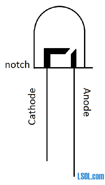
If you follow these rules you should get good service from your LED lighted equipment. Stray from them and you are likely to see how quickly an LED can be destroyed!
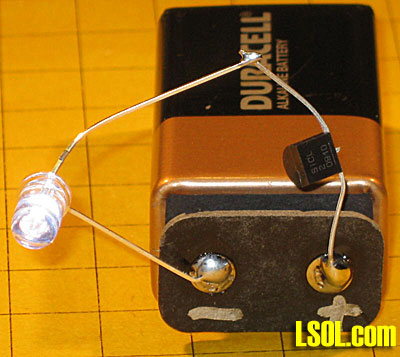
Limiting Current The most common way to limit the current that is allowed to flow through an LED is to place a resistor in series with the LED and its power source. A number of methods of determining the value of this resistor are explored in the LED article referenced above. Typical values range from 100 ohms to 1000 ohms depending on the LED and the voltage that is being used. This is one of the problems with limiting current with resistors, the higher the voltage the higher the resistance must be. This photo shows a very simple LED circuit composed of an LED, a 470 ohm resistor and a common 9 volt battery. Note that the resistor is connected to the positive terminal on the battery and to the anode on the LED. Even though it makes no difference which lead of the LED you connect to the resistor I have gotten into the habit of always putting the resistor on the anode side of the LED. That way I can tell at a glance which lead goes to positive and which goes to negative. 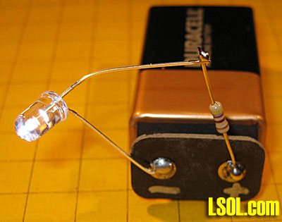
A Better Solution LEDs have become so common in our homes, consumer electronics and automobiles that it is not surprising that an integrated circuit has been developed that is aimed specifically at driving LEDs. This device is the CL2N3-G LED Driver from Supertex. It is inexpensive, even in small quantities, and is configured to deliver a constant current of 20 ma to an LED. The CL2N3-G can be ordered from Mouser Electronics for about $0.44. There is also a similar IC that delivers 25 ma, the CL25N3-G. The CL2N3 couldn't be easier to use. Just insert it in series with the DC power source and the LED. The TO-92 package has three pins but only the outside two are used. The center pin can be cut off. The positive voltage goes to pin VA and pin VB goes to the anode of the LED. Remember, the center pin, labeled NC, is not connected. 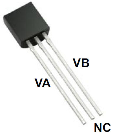
CIRCUITS
The simplest circuit utilizing the CL2N3 is shown below. The amazing thing about this device is that the battery, or other DC power source, can be as high as 90 volts and the LED will still see only 20 ma. 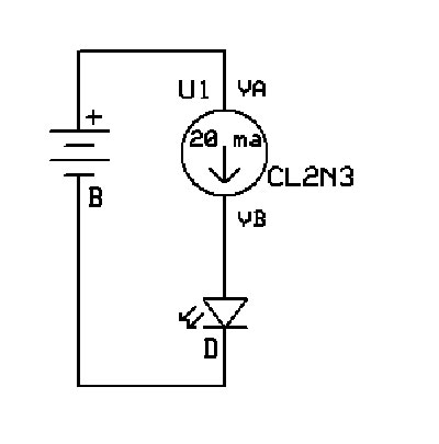
Here is a photo of the same circuit. Notice that the center lead of the LED driver has been cut off. 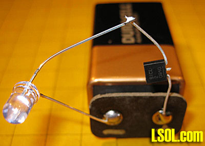
LEDs in Series
You may recall from one of my earlier articles on LEDs that they can be wired in series (see: LEDs 101 - The Basics). The beauty of using LEDs in series with the CL2N3 is that you do not need a current limiting resistor. All of the LEDs in the series will get 20 ma and all will light so long as the voltage supplied is high enough to deliver the required forward voltage to each LED. For example, if each LED requires 2.2 volts to light and you are putting six of these LEDs in series the voltage must be at least 6 x 2.2 or 13.2 volts. Any voltage at or above 13.2 will work. If your batteries supply 20 volts you could have as many as 9 of these LEDs in series. What a great way to illuminate the interior of a passenger car. 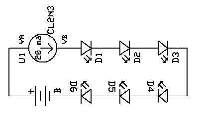 Here you can see four LEDs wired in series along with a single CL2N3. The circuit is powered by a bench power supply that is supplying 17.8 volts, shown on the bottom display. The top display shows that the circuit is drawing 0.02 amps or 20 ma, just as we would expect. 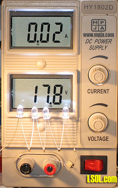
CL2N3s in Parallel
The CL2N3s can be wired in parallel should you want to supply more than 20 ma to your LED. This might be done if you were working with higher output LEDs like those that I used for the head lights for Mr. Rogers Trolley. Each of those extremely bright LEDs drew 60 ma. To safely drive them this circuit could be used: 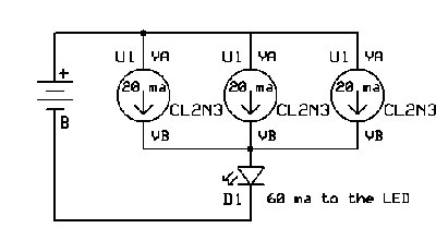
The next three photos show a 1/2 watt LED connected to 17.8 volts. The first photo shows this circuit with a single CL2N3. The meter tells us that 0.02 amps is being supplied to the LED. 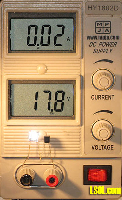 Here a second CL2N3 has been added to the circuit. It is wired in parallel with the first LED driver. The meter shows that 0.04 amps is being supplied as we would expect. Although it is difficult to see in the photo the LED is also considerably brighter. 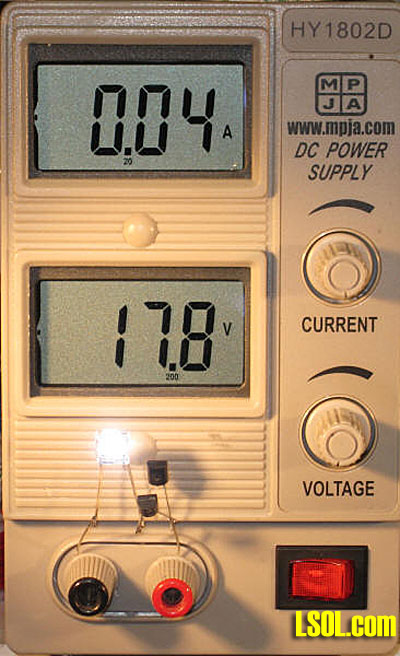 The last photo in this series shows three CL2N3's in parallel and 0.06 amps going to the LED allowing it to achieve its full brightness. 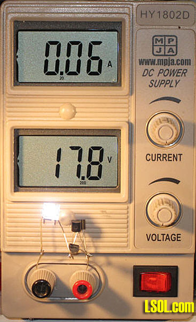
Conclusion
I think you will agree that the CL2N3 makes it simple to manage the use of LEDs. I encourage you to give them a try with your next lighting project. Please let me know if I can help!
| A Better LED Circuit |
| Great little article on LEDs for those of us who are electrically challenged on an easy way to use LEDs. |
| John Hill - 02/03/2010 - 05:02 |
| LED drivers |
| Dave, Great article. And one who has used LED's this may well be a god send. Two questions, as always, I have questions. How are the drivers different than the resisters? The instrument used to show the volts and amps looks very interesting and would be a great tool for teaching current. What is it? Thanks, Gary |
| gary condry - 02/03/2010 - 06:21 |
| Intro |
| Covering 'The Rules' as an intro into the article made it easier to follow along. Things have changed so much in the past 55 years in railroading, all for the better. |
| Rick Henderson - 02/03/2010 - 06:28 |
| LED Drivers |
| Hi, Gary - good to hear that you liked the article. A voltage regulator provides a constant voltage (a 7805, for example, provides 5 volts) and still needs a current limiting resistor when used with LEDs - one needs to do some math or experimentation to figure out the proper resistor. This device provides a constant current of 20 ma which is ideal for most LEDs. Makes life simpler as a resistor is not needed. The device I used in some of the photos is a power supply. One knob adjusts the voltage and the other cab be used to limit current. Nice box from Marlin P. Jones - about $60.00 - I use it all the time. See: http://www.mpja.com/prodinfo.asp?number=14600+PS dave |
| Dave Bodnar - 02/03/2010 - 06:39 |
| LEDs |
| Dave: Where can I find an LED simliar to the one you show in your article? Some places only sell them by the 1000's. Thanks, Colin |
| Colin Jameson - 02/03/2010 - 08:33 |
| LEDs |
| Colin - I get most of my LEDs directly from China - I also resell them in any quantity from 1 on up - I have white, warm white, amber, red, blue, green, etc in 3mm and 5mm sizes - drop me a private email (dave@davebodnar.com) for more detailed info. dave |
| Dave Bodnar - 02/03/2010 - 08:39 |
| LEDs and Track Power |
| Dave, thanks for a great article. You could not have made it any clearer. To use the driver with track power, it seems that all that's needed is a bridge rectifier to supply correct polarity to the driver. Is that right? Now I am eager to put interior lighting in some coaches. Bill |
| Bill Ness - 02/03/2010 - 09:53 |
| LED driver |
| A great tip, Dave. I've converted many of my passenger cars to LED lights and am very pleased with them. Does Radio Shack have these (or equivalent) drivers? I'm sure the shipping exceeds the cost of them ! Since I power my LED circuits from the track, I'll need a rectifier to keep the voltage flowing in the same direction regardless of train direction, but this seems a much smaller and easier construction. TIA. |
| Dick Friedman - 02/03/2010 - 10:12 |
| LEDs and Track Power |
| Bill - Glad you liked it! I would suggest putting an electrolytic capacitor on the output of the bridge rectifier so the LEDs don't blink on dirty track. dave |
| David Bodnar - 02/03/2010 - 11:15 |
| LED driver |
| Dick - Radio Shack does not handle them - I get mine from Mouser - the shipping does add up - I would suggest going together with some other folks so you can split the shipping. |
| David Bodnar - 02/03/2010 - 11:17 |
| how about PWC and reverse LED's? |
| Great tip, Dave. I know that as the voltage changes for speed to a motor the resistor to the LED would have to change too. But with this LED driver: that goes away. That is a wonderful thing. However I run pulse width control. Whenever the pulse stops the magnetic field in the motor sends a bit of reverse current out and illuminates the LED for the reverse direction. How can I extinguish this electronically and still use PWC? |
| Glenn Habrial - 02/03/2010 - 13:46 |
| how about PWC and reverse LED's? |
| Glenn - I would suggest adding a diode in front of the LEDs - that should block any reverse power that sneaks in. Just put the diode in series with one of the LED's leads. It does matter which way you insert it - try it one way and, if that doesn't work, turn it around! dave |
| David Bodnar - 02/03/2010 - 14:52 |
| PWC. and reverse (tender headlight) LED |
| Lets say it that way, I want it to light correctly when going in the reverse direction. (and I want the main headlight out when going backwards too) If I put in your diode then would it ever light? I was thinking of using series diodes as voltage droppers to get the LED to stay out when the back EMF voltage is forward biased on the LED. Would that work? since the PWC is relatively high pulse voltage then it would be enough to over power the diode gang for normal operation. |
| Glenn Habrial - 02/03/2010 - 17:57 |
| PWC. and reverse (tender headlight) LED |
| Glenn - I think that the diode should work but can't be sure without having the system on the bench - I have observed what you are seeing but have never spent any time trying to stop it. dave |
| David Bodnar - 02/04/2010 - 01:34 |
| Back EMF |
| Dave and Glenn, I am not sure if a diode by itself would do the trick. If the back EMF pulse is more then the trigger voltage of the diode it will still pulse the LED on, and if the diode was turned around the wrong way then the LED wouldn't light at all. I was thinking since the back EMF pulses are short then maybe a simple low pass filter with a small cap and resistor might work. Or a choke (coil) in the circuit to block the pulses. |
| David A. Maynard - 02/05/2010 - 17:32 |
Top of Page
|


