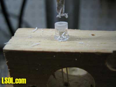
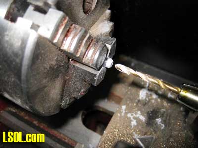
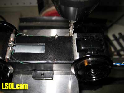
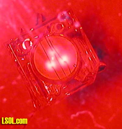
The lights at either end of the trolley presented a few additional challenges. The first was selecting LEDs. I wanted them to be very bright since some of the trolley's operation would take place in a lighted room at the hospital and I didn't want them to be overpowered by the room lights. More importantly I wanted lights that looked good. The typical 5mm bullet shaped LEDs are fairly long and would project farther out of the trolley than I wanted. The end plates on the trolley were made from shaped 3/32" Plexiglas and I didn't want an LED sticking very far out of the front or back of the plastic. In this case another new product filled the bill. In order to achieve greater brightness some manufacturers have started to put multiple LED junctions in one case. These are called multi-chip LEDs. The total light output from the three LEDs on the chip is blinding.
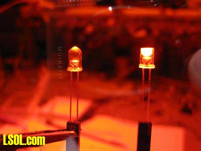
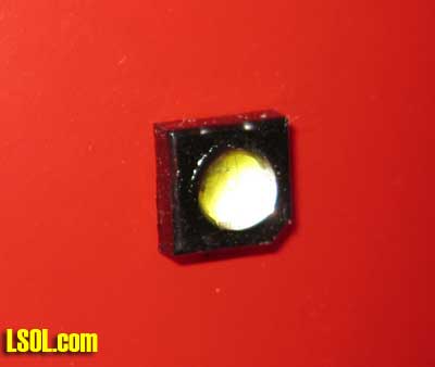
This photo of a multi-chip LED was taken through a filter and with the voltage way below what the LED needs to operate. If you look carefully you can make out the three separate diode junctions and the wires that connect to them.
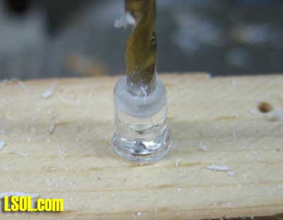
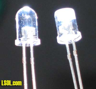
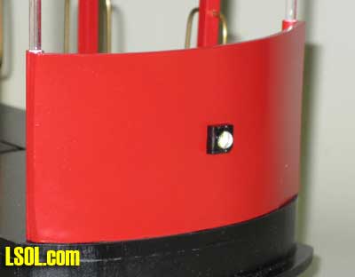
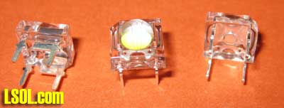
They can be extremely bright and come in a number of case configurations. The ones that I chose were ideal for this application since the LED has a square base and a small 5mm lens that barely sticks out above the base.
These LEDs have four leads coming out of the back. The leads are wired in pairs with the two smaller leads being anodes and the two larger leads being cathodes. Even though you only need to hook up one of each lead the fact that there were four leads really helped in mounting them to the plastic. I just drilled four holes, inserted the LED's leads and bent them over to secure the LED. I just had to make sure that I joined the two cathodes and the two anodes together before a drop of solder made them a permanent part of the trolley.
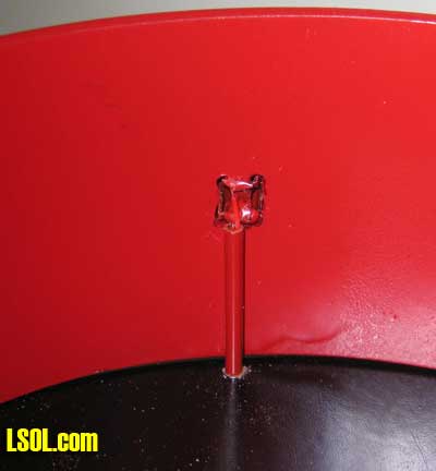
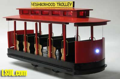
Thin (30 gauge) wire was soldered to the LEDs and routed through the trolley's base via a 1/16" piece of brass tubing. I also painted the square base of the LEDs black to make it look like a housing.
Directional Lighting CircuitThe circuit that controls the front and rear lights is a bit more complex but starts out with virtually the same components that we used on the clerestory. If we were satisfied with having both lights stay on whenever the trolley ran we could have just wired these LEDs in parallel with the clerestory lights and we would have been done.
I wanted to have directional lights that would have only the front light illuminated when the trolley was going forwards and only the rear light lit when it went the other way. This would accomplish two things. First it would look better as there is little sense in lighting the track behind you. More importantly it would preserve the power in the capacitors so that the lights would be able to stay on longer when at the end of the track. I also wanted a circuit that would utilize only one additional set of supercaps as they are fairly large and space was at a premium under the trolley.
The circuit adds a few components to what we used for the clerestory lighting. LEDs D3 and D4 are at opposite ends of the trolley. R1 and R2 are 30 ohm current limiting resistors that keep too much current from destroying the LEDs. The components that actually turn the appropriate LED on or off are D5, D6, R5, R6, Q1 and Q2. When the polarity on the track is set one way one of the diodes conducts turning on the transistor it is attached to. When the polarity reverses the other diode comes into play. The transistors that I used are a special type of transistor called Mosfets (metal oxide silicon field effect transistors). The work just like regular transistors but have one characteristic that makes them very useful in this application. I'll explain more about that in a moment.
We want one of the transistors to turn on when the trolley goes one way and the other when it reverses. That is taken care of with D5 and D6. But we also want that transistor to remain on once the trolley gets to the end of the track where it completely loses power until the polarity is reversed by the BARC controller. Here is where capacitors C3 and C4 and resistors R3 and R4 come in. When one of the transistors is first turned on the capacitor connected to its base (note that the base is called a gate on a Mosfet) charges. When the trolley ends its run the charged capacitor keeps the transistor "on" for a time even though track power is gone. The resistor that is paired with the capacitor slowly discharges the capacitor so that the LED goes out after a few minutes. Remember that we don't want to completely discharge the supercaps if we can help it.
The last two components, R7 and R8 , keep both the lights from being on at the same time. When LED D4, for example, is on R8 is connected to ground and discharges capacitor C4 in a second or two extinguishing the LED. Similarly R7 will discharge capacitor C3.
The amount of time that the LEDs stay on after the trolley has gotten to the end can be adjusted by changing resistors R4 and R3. Larger resistors discharge C3 and C4 more slowly leaving the lights on longer. Smaller value resistors discharge the capacitors more quickly.
To review, when D5 conducts it turns on transistor Q2. Capacitor C3 also charges. When the trolley hits the end of the track D5 no longer supplies power to the transistor and it would go off extinguishing LED D4. This does not happen because of the charge on C3 which keeps the transistor on.C3 slowly loses its charge through R4 eventually turning Q2 off. If C3 is not fully discharged when the trolley reverses resistor R7 will quickly discharge C3 as soon as Q1 is turned on.
Now to the reason for the Mosfet transistors. When I first built up this circuit I used standard 2N2222 transistors to turn the LEDs on or off. Everything worked fine, but the LEDs only stayed on for a short time (1 or 2 seconds) after the track power was lost. It seemed that C3 or C4 were discharging very quickly. I tried larger capacitors but that only helped a bit. I did some research and found that regular NPN transistors like the 2N2222 draw a good bit of current through their base lead. That is what was discharging the capacitor. It was losing its charge through the transistor. Some more research led to the use of Mosfets which draw virtually no current through their gate lead. Problem solved!
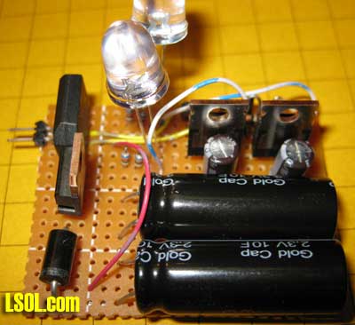
Circuit PrototypeThe prototype circuit was built on a small piece of circuit board. The two supercaps are the large black objects at the bottom. The bridge rectifier is in the upper left, below it is the voltage regulator and diode D2. In the upper right are the two Mosfets. Behind them are capacitors C3 & C4. Two 10mm LEDs were temporarily installed for testing.
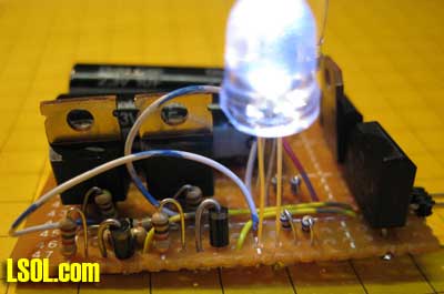
When viewed from this angle you can see the Mosfets more clearly as well as a number of resistors and diodes. The pairs of small resistors in the bottom right are 60 ohms each. They are wired in parallel to give me two 30 ohm current limiting resistors for the LEDs.
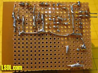
The wiring on the back of the board is not pretty but it works perfectly!
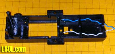
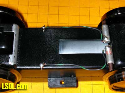
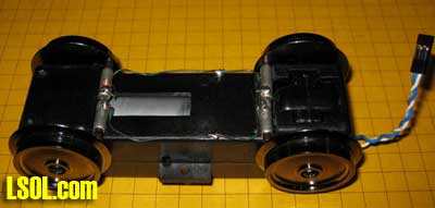
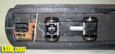
Here the board has been installed under the trolley.
ConclusionIn operation the trolley's forward facing headlight and clerestory lights come on when the BARC applies power to the track. When the trolley gets to the end and hits the section of track with a diode in it the trolley stops but the clerestory lights and the forward facing light stays on. If the trolley stays at the end for more than 2 minutes the head light goes off. If it reverses before that time elapses the other head light goes on and the first one goes out in a second or two. I think you will agree that the lighting is more prototypical and more interesting to watch!
Even though the project described here is designed for a point-to-point route the same concepts and the circuit from the clerestory can be used on any locomotive or piece of rolling stock where you want lights to remain on even after track power has been removed.
I hope you learned something from this discussion and the circuits that are described. I can assure you that I learned a great deal in the process of designing it!
If you have difficulty locating any of the items described in this article please contact me as I have a number of them on hand.
| Craftsmanship |
| Dave, Thanks for a very well-written article. It is clear enough that most folks can follow the directions with ease. Later, I may use your article to build my own. Mark |
| Mark Douglas - 01/28/2009 - 06:49 |
| Well Done |
| Dave, Well presented. Well illustrated. Well done! Bruce |
| Bruce Watkins - 01/28/2009 - 07:05 |
| LED Modification |
| Dave, Another great article. I can sure use your technique for modification of LEDs. Now I'll have to go back and redo the LEDs used to light passenger cars. I didn't realize that the LEDs could be modified without destroying the LED. |
| JD Miller - 01/28/2009 - 07:25 |
| Electrical Pick-ups |
| Great article Dave. I have always learned a great deal from your articles and presentations at the ECLSTS. My question: How can I get those electrical pick-ups you used. |
| Lance Cave - 01/28/2009 - 07:57 |
| Schematics |
| Dave, Like your article and the modifications to the diodes to defuse the light. However, the links to the schematics don't work. |
| Bill Albrecht - 01/28/2009 - 08:00 |
| WOW |
| WOW Dave, I wish I had taken a better look at this at your house last week. I know I would have love to have seen the top lights on. I thought it was not running just yet. I look forward to getting the layout up and running too. |
| Clifton MunzPhelps - 01/28/2009 - 08:44 |
| LED Modification |
| Dave: Great article as usual. Never thought about altering an LED, great idea. |
| Jim O'Connor - 01/28/2009 - 10:22 |
| Power Pickups |
| Lance - the pickups are a standard LGB part - they are still available at hobby shops and on the net - look for part # 63193 - AristoCraft makes something similar. dave |
| Dave Bodnar - 01/28/2009 - 11:05 |
| Schematic links |
| Bill - I sent Jon a note about the schematics early this morning - hopefully he will correct that directly. dave |
| Dave Bodnar - 01/28/2009 - 11:06 |
| Links to schematics |
| Links to schematics should be working. |
| Jon DeKeles - 01/28/2009 - 11:40 |
| Trolley lighting |
| Mr. Bodnar, I have enjoyed reading your articles on using LED's and circuits to control them. This article is again informative and definitely educational. Learning how is great, but knowing why is better. Thanks. What type of lathe and mill are you using? |
| Larry J. Tomko - 01/30/2009 - 15:10 |
| Lathe & milling machine |
| I am pleased that you enjoyed the articles - the lathe and milling machine are both from Harbor Freight - whenever they come up with a super sale I just have to get something and these two units do not disappoint - great value for the price! dave |
| Dave Bodnar - 02/01/2009 - 02:39 |
|
| Dave: couldn't you use a positive and negative 5 volt regulator for the directional lighting? As usual a great job. Nice article EMIL |
| - 04/09/2009 - 02:49 |
Top of Page