Power, Sound, R/C
:
Lights / LED
LEDs 101 - The Basics
Jun 20, 2007


By David Bodnar
LSOL.com Electronics Editor |
Author
Bio
LEDs have rapidly taken the place of incandescent light bulbs in many, if not most, model railroad applications. Let's take a few minutes for review and a few minutes more to see if we all can learn some new tricks with these fascinating and useful devices.
|
LEDs 101 Introduction LEDs have rapidly taken the place of incandescent light bulbs in many, if not most, model railroad applications. Although LEDs have been the topic of many LSOL articles, questions that I see in the forums and that I receive in emails tell me that a review of their characteristics and use is in order. In addition I have discovered a number of interesting LEDs and ways of using them that I don't think have been presented here before. Let's take a few minutes for review and a few minutes more to see if we all can learn some new tricks with these fascinating and useful devices. Review - Physical Characteristics LEDs are available in a number of different sizes and shapes with most being round topped cylinders that are either 3 mm or 5 mm in diameter. These sizes are also commonly referred to as T1 (3 mm) and T1 3/4 (5 mm). The body of most LEDs is made of plastic that is either the same color as the lit LED, generally referred to as a diffused LED, or of a completely transparent plastic. As a rule the clear LEDs are brighter than the diffused ones. The two LEDs on the left in this photo are diffused, the two on the right are clear. You can see the relative sizes of the 3mm and 5mm units, as well. 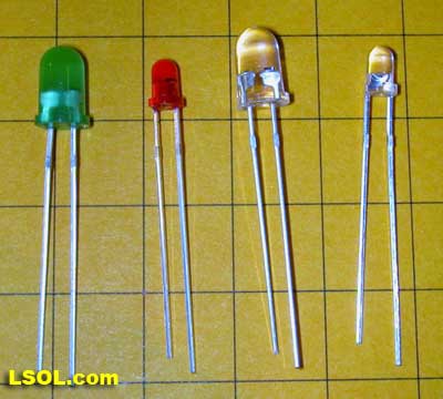
Colors that are commonly available include red, orange, yellow or amber, green, blue and white. Infrared and ultraviolet LEDs are also available as are multicolored devices that can light with two or more colors.
An LED's color is frequently expressed as its wavelength. The shorter the wavelength, the closer the light is to the violet end of the spectrum, the longer the wavelength the closer it is to the red end. (Do you remember "Roy G. Biv"?) A typical red LED has a wavelength of 660 nm (nanometers or billionths of a meter) 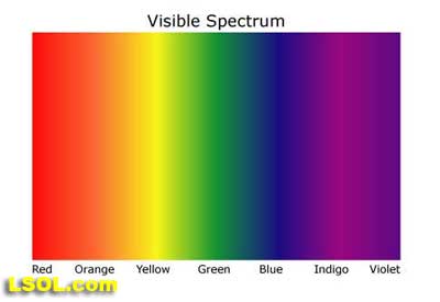
Most LEDs have two metal wires extending from the back of the plastic body where they can be connected to a source of DC power. The longer lead is called the anode and is connected to the positive terminal of the power supply or battery. The shorter lead is the LED's cathode and is connected to negative. The base of the LED generally has a flat area next to the cathode which helps with lead identification if the wires have been cut. You can also identify the cathode by looking carefully at the insides of the LED. The cathode connects to the part that contains a dish shaped lens. Note that this is much easier to identify on the clear, non-diffused LEDs. In the photo below the cathode is on the right and the anode is on the left. If you look carefully you can see the dish in the center of the photo and the flat spot on the right side of the base of the clear plastic. 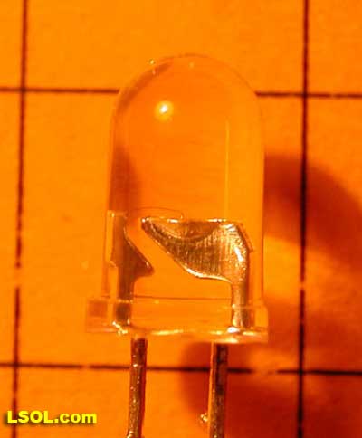
Review - Other Properties LEDs are usually rated for size, color, brightness, voltage and current. Radio Shacks' LED # 276-309 has these properties listed: - Size: T-1-3/4 or 5mm
- Typical voltage: 1.7, with a maximum voltage of 2.4V
- Typical wavelength: 660mm
- Typical MCD: 800
- Viewing angle: 40 degree
- 20mA (max)
The voltage is a minimum of 1.7 volts and a maximum of 2.4 volts. This means that the LED will start to emit light at 1.7 volts. The upper limit of 2.4 volts does not mean that you could not power this LED with a higher voltage, it just indicates that you must include a resistor in the circuit should you use a higher voltage. The wavelength listed by Radio Shack is 660 mm. This is an error. It should read 660 nm. As mentioned earlier the wavelength refers to the color of the LED. The brightness is given as 800 MCD (microcandelas). This is not a particularly bright LED. You couldn't use it for much more than an indicator or marker light. The viewing angle is 40 degree, a fairly wide beam. The light emitted from some LEDs is focused to an angle of 30 degree or less. The most critical item in the list is the current limit which is given as 20mA (maximum). If more than 20mA is allowed to flow the LED will heat up and, if sufficient current is allowed to flow, the LED will be destroyed. Resistors are generally used to limit the amount of current that can go to an LED. The value of the resistor that is needed can be determined in a number of ways. Please see last year's article: A Simple Constant Brightness LED Light for a very detailed discussion of how this can be done. Review - Advantages: - LEDs consume much less power than light sources that rely on a heated filament to product light
- LEDs produce little or no heat
- They have a very long, almost infinite, life if installed and powered correctly
- Many LEDs achieve full brightness at a much lower voltage than incandescent lights
Review - Disadvantages: - Most LEDs only work from DC power.
- LEDs require a more controlled power source (voltage and current) than do incandescent bulbs
- Most LEDs, especially the bright ones, emit a focused light beam that may not be appropriate for all applications
- Many white LEDs have a very noticeable bluish tint to them
- LEDs can be more expensive than incandescent bulbs
A Simple LED Tester In theory one should mathematically or experimentally determine the proper current limiting resistor for a particular LED being supplied with a particular voltage. In reality a 470 ohm to 1000 ohm resistor will work with just about any LED for any voltage we are likely to use in garden railroading. There is a simple circuit that you can make that takes advantage of this fact and will safely test most LEDs. The test circuit that I use most often is battery operated and consists of just a few parts. This illustration below shows the schematic for the tester. The LED is labeled D1. Its anode goes to the left and its cathode goes to the right. R1 is the 470 ohm current limiting resistor. The 9 volt battery is at the bottom with its positive terminal to the left. 
A 9 volt transistor radio battery, 9 volt battery power clip (Radio Shack #270-324), a 470 ohm resistor and a two conductor plug is all that is needed. The two conductor plug makes it a snap to insert an LED into the circuit for testing. These plugs can be salvaged from the innards of an old desktop computer. There are usually a number of these plugs inside of the computer's case. They are used to connect the front panel switches (power, reset, etc), speaker and LEDs (hard drive, power, etc) to the computer's motherboard. The one shown below was used to connect the computer's hard disk LED to the motherboard. 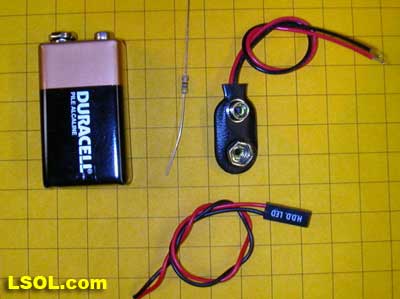
To make this test unit shorten the leads on the 470 ohm resistor to about 1/4" and solder one of them to the end of the positive (red) wire of the battery clip. Solder the other end of the resistor to one of the wires from the computer connector plug. Ideally this should also be red but any color will do so long as you remember that the lead with the resistor soldered to it is the positive supply voltage that will connect to the longer wire on the LED, its anode. Solder the other (black) wire from the battery clip to the remaining wire from the computer plug. You may want to use heat shrink tubing or tape to insulate the exposed wires. 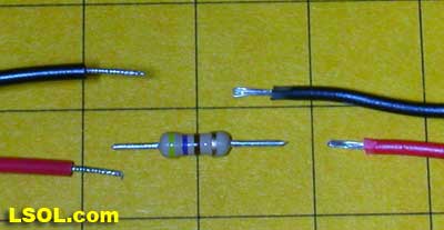 Here you can see two pieces of heat shrink tubing ready to slide over the joints. 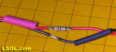
To test an LED insert its anode lead (the longer one) into the positive end of the computer plug and the shorter lead (the cathode) into the negative side of the plug. If all is connected properly the LED should light. Note that connecting the LED backwards will not harm it because of the current limiting resistor. If it does not light try switching the two leads. I have used this test unit with literally thousands of LEDs over the years and have never damaged an LED with it. 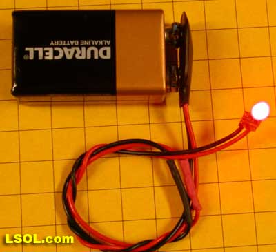
An even more compact tester can be made by salvaging the terminals from a dead 9 volt battery that can be used in place of the battery clip. These photos shows how I made such a tester. To salvage the connector from a dead 9 volt battery carefully trim the metal away from the top of the battery and remove the clip. Most 9 volt batteries have two flat wires that connect to the cells inside of the case. Be careful when discarding the remainder of the battery as the twisted metal case that remains is full of sharp edges. 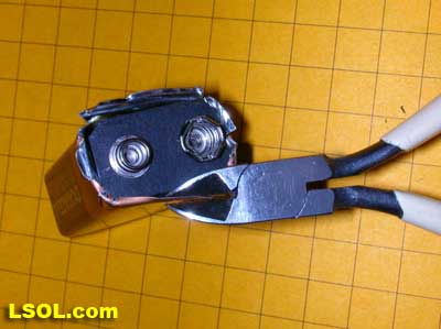
Here is what is inside of a Duracell 9 volt battery. Shown is the back of the clip (on the right) and the 6 individual cells (the green cylinders on the left) that are wired in series to supply 9 volts. Note to tinkers: These cells are a great source of small 1.5 volt alkaline cells! They are significantly smaller than AAA cells. 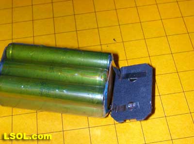
Here the 470 ohm resistor has been soldered to the back of the clip. Note that the resistor goes to the female part of the clip which connects to the male (positive) contact on the battery. 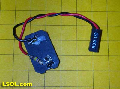
To insulate and provide strain relief I coated the top of the whole thing with hot melt glue. 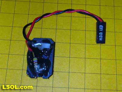
Here it is during another successful LED test! 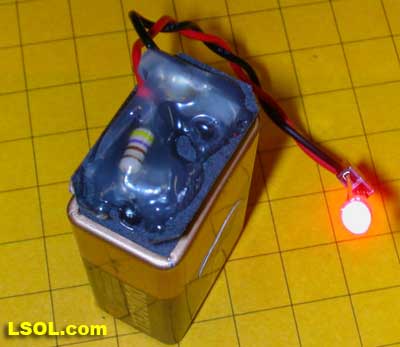
Wiring Multiple LEDs in Parallel When multiple LEDs are needed, perhaps to illuminate the interior of a passenger car or a building, they can be powered from a single power supply by wiring them in parallel. Accepted practice is to wire each LED with its own current limiting resistor as in the diagram below. Since each LED has its own current limiting resistor, which need not be the same value, you can mix different brands and colors of LEDs while having each retain its full brightness. 
The number of additional LEDs that can be added to this parallel circuit is only limited by the amount of power that your battery or power supply can provide. Even with just a 9 volt transistor battery 10 or 20 LEDs should not be a problem. The battery may not last too long with 20 LEDs but it will light them! If space is an issue you can try using just one current limiting resistor for multiple LEDs. The only restriction is that all of the LEDs need to be identical. Even then, there is no guarantee that all of the LEDs will shine with the same intensity if only one resistor is used. I have successfully used this technique for a multiple-LED beacon on top of a model radio tower. Note where the resistor is placed, close to the battery's positive terminal, so that it limits the current going to each of the LEDs. 
Wiring Multiple LEDs in Series If care is taken to match LEDs and the current limiting resistor, multiple LEDs can be wired in series. This provides two advantages. First, it can simplify wiring as the LEDs can be daisy-chained one to the other. Series LEDs also have the potential to draw less current than their parallel wired counterparts thus extending battery life should they be powered in this way. The voltage that is applied to the series of LEDs must be at least sum of each LED's minimum voltage or none of the LEDs will light. For example, using five of the Radio Shack LEDs above you would need a minimum of 1.7 volts X 5 = 8.5 volts to light the LEDs. 
Some experimentation may be in order to find the best value for resistor R1. The more LEDs you place in series in the above circuit the smaller the value of the resistor can be. In fact, you can eliminate the resistor completely at some point and still operate the LEDs safely.
Flashing LEDs An LSOL member asked a question in the forums some months ago about a circuit that could be used to flash a red LED on top of a water tower. He was looking for a simple and inexpensive way of doing this and my first thought was to use a PICAXE to control the LED and its flashing rate. Although other devices, such as the venerable 555 timer, could be used the PICAXE provided an inexpensive and easily configured flash controller. Some weeks later, with this idea fresh in my mind, I came across a number of self-contained flashing LEDs on the web page for All Electronics. I didn't have much hope that they would provide a very good solution but I ordered a few different colors and sizes of flashing LEDs to satisfy my curiosity. When they arrived I experimented a bit and found that my first concerns about their usefulness were justified. They all flashed, just like advertised, but the rate was fixed, the time on & time off were not balanced and most of them were dim. I put them aside for a few days until I had a thought: could I use one of these flashing LEDs to cause another, brighter LED to flash in unison? A few experiments proved that this was, indeed, possible. In fact, it worked very well This diagram shows how you can wire a flashing and a non flashing LED so both of them flash together. It really couldn't be much simpler since most of the flashing LEDs don't even need a current limiting resistor if you supply them with 5 volts. Nothing more is needed than the two LEDs, wired in series anode to cathode, and power. 
In the photo below I am using 4 of the tiny 1.5 volt cells from a disassembled 9 volt battery to power the above circuit. The cells, from the nearly dead 9 volt battery, supplied just under 5 volts. The flashing LED is the red one at the bottom. Note the dramatic difference in brightness between the two LEDs. The green one is a standard high intensity LED that is flashing in unison with the red one. I intentionally left the wires long so that you could see what is connected where. The longer lead from the green LED goes to the positive wire from the battery. The shorter lead from the red LED goes to the battery's negative wire. The longer lead from the red LED is soldered directly to the shorter lead from the green LED. 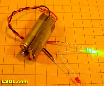 To use 9 volts or more with the above LEDs just insert an appropriate current limiting resistor in series with one of the power leads. 
Multiple Flashing LEDs I experimented a bit adding one then another bright green LED in series with the other two. Each time I had to increase the voltage a by about 3 volts as the green LEDs will not illuminate until each one sees nearly 3 volts. I have to admit that I was amazed by the results from experiment you see below. There are 5 bright green LEDs and one red flasher, each wired anode to cathode with no current limiting resistor at all. The circuit is being supplied with 15 volts. The amazing thing is that the red LED's flashing circuitry did not fry from the power that is going through it. I suppose you could try adding a few more LEDs but as it is this array would really brighten up a runway, building beacon or other structure. As a test I let this run on the bench for nearly a week and it worked just fine. Chances are it will operate indefinitely. 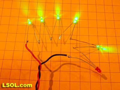
The schematic below reinforces the simplicity of this circuit. 
Video In this video you see an array of flashing LEDs. The five green and one red that we just covered are there at the top of the screen. The board at the bottom has five different flashing LEDs each of which is wired in series with a non-flashing LED. The row of LEDs at the bottom are the flashers. Those in the center of the board are the standard ones. The two red flashing LEDs (one 3 mm and one 5 mm) at the left are from All Electronics and the three flashing LEDs ( 5 mm green, 3 mm red and 5 mm bright red) at the right are from Futurlec. Note the dramatic difference in the video between when the room lights are on and when they are off. I think these would look super outside after dark! Watch the Video
Conclusion I hope that this article has helped to unravel some of the mysteries associated with LED use and operation. I also hope some of you have a chance to experiment with the LED wiring options, flashing LEDs and other topics that were presented. I am sure that there are still questions I have not answered so fell free to let me know how I can help. Additional Reading A Mars Light for Your Large Scale Engine
Make Some Working Ditch Lights
5 Volt Power for Railway Electronics Top of Page
|


