Scratch & Bash
:
Engines / Rolling Stock
G-Scale Drag Strip Controller
Oct 8, 2008
By David Bodnar LSOL.com Electronics Editor
Author
Bio
Why on earth would anyone want a drag strip controller for a model railroad? What is this, a trick question? The answer is simple, what could be more fun than a little friendly competition racing locomotives on a G-Scale drag strip??? Come see why...
Introduction
Why on earth would anyone want a drag strip controller for a model railroad? What is this, a trick question? The answer is simple, what could be more fun than a little friendly competition racing locomotives on a G-Scale drag strip???
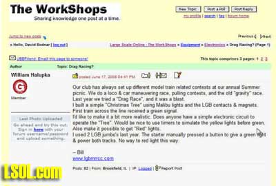
When LSOL member Bill Halupka mentioned on the LSOL forums that he had set up a simple drag strip timer for the LGB Model RR Club of Chicago picnic it certainly got my attention. I became even more interested when Bill asked if it was possible to build a more sophisticated controller that would do more than just determine the winner.
What transpired for the next few weeks clearly demonstrates the power of the collective intelligence of the LSOL.com online community. More than 60 forum postings helped me through the design / prototype / test / revise cycle a number of times.
A number of LSOL forum regulars chimed in with ideas and suggestions for refinement. We even discovered that Todd Brody and his wife have spent many hours drag racing their own cars. He kept the project on track and did his best to guide the development towards a realistic conclusion.
It took nearly five weeks but at the end of that time a working unit was sent to Bill for use (and more testing!) at the picnic in Chicago.
Before one embarks on the development of a new electronic device it helps to have an objective or two that will keep you on the right track! The statement below guided us throughout our discussions in the forums:
The objective of this project is to design and construct a controller that will manage a G-Scale drag strip where two locomotives will race each other over a fixed distance. The controller will make sure that the two competing engines are staged properly at the start and that they both start fairly after the "Christmas Tree" lights have reached green. The controller will determine the winner and will display the reaction time of each competitor and the time required to complete the run.
Operational Scenario In addition to the objective an operational scenario was developed that gave a vision of what the completed controller would do and how it would be operated:
Two parallel tracks are set up on a level surface. A few feet from one end a "Christmas Tree" light pole and two IR sensors are placed between the tracks. Near the other end of the track another set of IR sensors is used to determine the winner. Sufficient track is left after the sensors at the end to allow competitors to bring their engines to a safe stop.
A five conductor cable connects the far end sensors to the controller. A second five conductor cable connects the start sensors and a ten conductor cable connects the "Christmas Tree" lights to the controller. The controller itself connects to 7-12 volts DC and has two buttons on it, one labeled Start and one labeled Reset. A separate power supply that is appropriate for the voltage of the Christmas Tree's bulbs attaches directly to the lighting circuit.
Each track is connected to its own power supply and speed controller. The competitors control starting and stopping of the engines and use the throttle to determine their speed.
To start a race:
The race official presses the Reset button on the controller.
The lights on the entire Christmas Tree flash briefly then the Blue lights on the Christmas Tree flash 3 times indicating a successful reset.
The Blue lights at the top remain lighted to signify that neither engine has been staged.
Engines are placed on the track behind the tree and moved forward until the Red light in their lane illuminates. This can be done either manually or with power.
Each engine is then moved a short distance backwards until the Red light in its lane goes out. This is the start position.
When both engines have been properly staged both Blue lights are off.
The race official presses the Start button on the controller.
The Christmas Tree begins to signal the start of the race. The top Amber light lights, 0.5 seconds later it goes out and the second Amber light lights, 0.5 seconds later it goes out and the third Amber light lights, 0.5 seconds later it goes out and the Green light lights.
When the Green lights light the race begins and each competitor starts their engine.
The controller notes if either engine crosses the start sensor before the Green lights light. If this happens the Red light in that lane lights and that lane is disqualified.
Timing for each lane starts when the first sensor is crossed and stops when each engine crosses the end sensor.
After the race the Blue light atop the tree lights to indicate the winning lane.
The results are not reported until both end sensors are crossed. This will necessitate manually breaking one of the end beams if one engine breaks down.
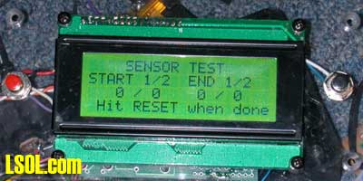
The LCD display gives the reaction time and total time (in seconds, tenths and hundredths) for each lane.
Pressing the Reset button clears all data and restarts the system.
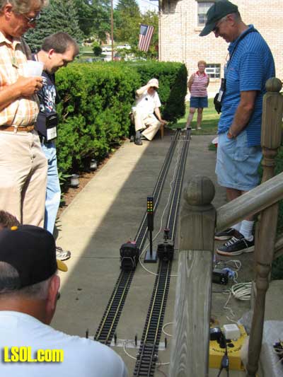
Video
This video shows a race that took place at this year's Pittsburgh Garden Railway Society picnc. The controller can be see just off to the right once the engine passes. The "Christmas" Tree counts down and the competitors start on the green light. You will also note that the blue light in lane 2 is illuminated at the end indication that it was the winning lane.
<Right Click the image below and select "Play">
See video and photos from the Chicago eventHardware The hardware for the unit is composed of three major subsystems, the sensors, the Christmas Tree lights and the controller.
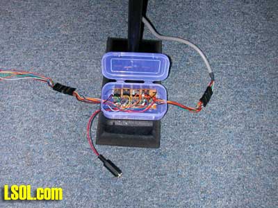
There are four separate sensor units, two at the start and two at the finish. Each sensor is made up of an infrared emitter and an infrared detector. The emitter is across the track from the detector. When an engine or other object prevents the infrared from illuminating the detector this is noted by the controller. The infrared light is pulsed at 38 KHz to minimize false readings from other light sources. The only two situations that can blind the detectors are when direct sunlight falls on the detector or when they are exposed to the flash from a camera. This type of sensor has been discussed in many other articles including Garden Railway Sensors, Part III and Automatic Switch Project, Part IV, Sensing Train Location.
In this photograph the infrared emitter is on the right and the detector is on the right. Note that the sensors are built low, just above the rail, so that they typically detect either the locomotives lead wheel or its cow catcher.
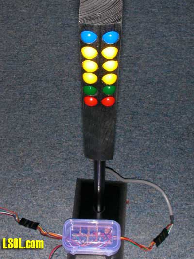
The Christmas Tree can be made from a variety of materials and can use a number of different types of bulbs. The one I made for the prototype utilizes 12 Malibu light bulbs that each draw 7 watts at 12 volts. Since the microcontroller that runs the system cannot directly control bulbs that draw that much power an intermediate controller board that contains 8 power transistors is used as an interface between the bulbs and controller. You may notice that there are 12 bulbs but only 8 power transistors. This is because the three pairs of amber bulbs and the pair of green bulbs are wired in parallel and always come on together. Only the two blue bulbs and the two red bulbs are controlled separately.
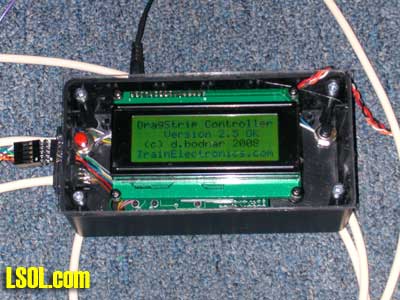
The controller connects to the sensors and the Christmas Tree unit. It has two buttons, Reset and Start, that control its operation. The 4 line LCD display give the operator prompts and shows the competitor's reaction time and run time to the end of the track.
Software The software that controls the unit is written in PIC BASIC. Its main routines include
Initialization
Staging
Race start
Race timing
Displaying results
Testing sensors
Initial Setup
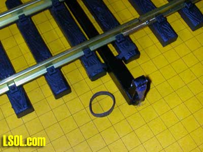
Place the Start and Finish sensors under each track being careful to place the sensor for lane 1 under track 1 and the one for lane 2 under track 2.
I have had good luck placing a small rubber band under each sensor then onto the adjacent ties to hold them firmly in place.
The rubber bands I use are made from old bicycle tubes (road bike tubes are best as they are smaller)
Connect the RJ-11 connectors from each set of sensors to the appropriate connection receptacle on the controller.
Connect the "Christmas Tree" lights to the connector on the controller being careful to observe polarity by aligning the sliver markings on the plug and receptacle.
Connect power to the "Christmas Tree" power board (the separate jack coming out of the small plastic box that goes to the tree)
Connect power to the controller
Testing the Lights and Sensors
Once everything is connected you can test the tree lights by pressing and releasing the Reset button. The lights will briefly illuminate in this order:
Blue 1
Blue 2
Both Amber 1
Both Amber 2
Both Amber 3
Both Green
Red 1
Red 2
Press Reset again and, while the copyright page is on the display, press the Start button. This will take you to the Sensor Test screen.
Briefly place your hand across each of the sensors. While blocking a sensor you should see the count for it increase rapidly. Note that this count only goes to 255 then resets.
Confirm that the sensors are working and are in the proper lane.
Testing Power to the Track
Connect power to each track and test an engine on each track.
Note the transformer setting that sends the train in a forward direction. Switch power lines if it is not correct.
If cut track with diodes is used at either or both ends remember that power must be applied between the cut sections, not at one end.
Remember that there is no connection between the timing system and the power to the track. Each competitor should be able to independently control their engine.
Running a Race
Place an engine behind each of the start sensors
Press the Reset button on the controller
Wait till the copyright screen clears and it displays "Press Start to Begin Staging"
Press the Start button. Note that both blue lights are illuminated indicating that neither lane has been staged
Manually move one engine forward towards the sensor until the red light lights indicating that it is blocking the sensor.
Move it back just enough to completely extinguish the red light. The blue light will go out, too.
Do the same with the other engine
Once both blue lights are out the display shows "Press Start to Race"
Remind the competitors that the timing starts when they cross the sensor and that crossing the sensor before the green light is lit will constitute a false start lighting their lane's red light.
Press the Start button to start the countdown.
As the engines cross the start sensor the display shows the reaction time
Once both engines have crossed the finish the race time is displayed.
The blue light shows the winning lane.
Press Reset to start another race
Race Standards
Setting standards for locomotives that race is beyond the scope of this article. I would suggest that this is something that the LSOL community can determine and publish so that other model railroad racers can benefit from their ideas and experiences.
Enhancements & Other Observations
Isolated Track I did a few things during the development of this system that served to make testing easier. The first was to cut a rail on each track which isolated it, electrically, from the rest of the track on the drag strip. This was done so that a train moving towards the end of the track would automatically lose power when it got past the last sensor. In order to allow me to bring the train back to the start for another test a diode was placed across the cut section. The diode was oriented so that power flowing in the direction that would cause the train to go forward would be blocked but power that would run the train in reverse could flow. More information on placing these diodes can be found by clicking here. I also put a similar cut section at the start of the track so that I could simply bring the engines back at high speed without worrying about turning the power off.
LED Based Tree
If most of your running is going to be done indoors you don't need to use the 8 transistor power board that is necessary to illuminate Malibu bulbs. You may also eliminate the power supply that powers these incandescent bulbs and use the same power supply that powers the controller to illuminate the LEDs.
Future Enhancement: More Prototypical Staging Lights
When full scale cars stage at a 1:1 drag strip their position is set with a pair of smaller yellow lights. These lights may be added in a future revision of the circuit board. LEDs may be sufficient for this purpose which will simplify adding them.
Future Enhancement: Top Speed Computation
The top speed of each competitor's run down the track is something that a drag strip controller should be able to do. Unfortunately adding that capability requires an additional pair of sensors at the end of the track. The microcontroller that I am using ran out of inputs during the circuit's design and there was no where to hook up another two sensors. A future revision of the circuit may be able to multiplex some of the input / output pins allowing for this to be added.
One other complication that would have to be dealt with is a software / programming issue. As you may know I have developed a rather sophisticated multi-scale speedometer for model railroad use. A good bit of its program area is dedicated to allowing the user to set the scale (from 1:1 to "Z" @ 1:220) that will be used when the speed is reported. Without some testing and time experimenting I am not sure if there is sufficient memory space on the microcontroller to allow addition of these routines.
Future Enhancement: Timer Speed Adjustment
The timer that is used to track the engines on their trip down the track uses the internal clock in the PIC microcontroller. While this timer is fairly accurate changes in ambient temperature and input voltage have the potential to throw this off a bit. I would like to add a simple routine that would allow the end uses, through a new setup routine, to adjust this timer up or down to give more accurate timing results.
Future Enhancement: Your ideas?
As noted earlier the real beauty of this project has been its development by a collaborative group of interested model railroaders. With this in mine the most important future enhancement ides will come from you, the LSOL community!
Drag strip
How lucky are we to have someone with these electronic abilities, willingness to design it, try it and perfect it. But most of all willingness to share it.
You the man Dave :-)
KC
KC - 10/08/2008 - 12:24
Drag Strip
Thanks for the kind words, KC - the good news is that it is great fun for me - keep the ideas and challenges coming!


.jpg)