Power, Sound, R/C
Multi-Scale Wireless Speedometer
Jul 5, 2006


By David Bodnar
LSOL.com Electronics Editor |
Author
Bio
I have been very pleased with the operation of the multi-scale train speedometer described in my recent article. "Is Your Train Speeding?" Large Scale Speedometer. There was one thing missing: Wireless Connectivity that would provide real time speed reports.
|
Multi-Scale Wireless Speedometer 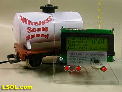 I have been very pleased with the operation of the multi-scale train speedometer described in my recent article "Is Your Train Speeding? Large Scale Speedometer". There was one thing missing: Wireless Connectivity that would provide real time speed reports. You may recall that the speedometer described in that article utilized two track-side sensors to determine a passing train's speed. 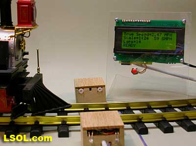
Since it depended on stationary sensors it could only give a train's speed at one location at a time. Of course you could move the speedometer and sensors around your layout but there are times when it would be useful to have a real time speed report to answer questions such as "How much does the train slow down as it struggles up a steep grade?" or "Does the train slow down significantly as it goes around a tight curve?" I came up with a number of ideas for providing real time speed including: - Placing the speedometer's display on a flatcar facing to the side. A viable option but one would spend a good bit of the day chasing the train around the yard and trying to read the speed off of the display. Good for fitness, but not a particularly nice way to spend an afternoon!
- Using a number of bright LEDs to flash out the speed from an on-board display as I had done with the Basic Auto Reverse Controller that I wrote about a few weeks ago. A better option but still not ideal.
- Using a loud beeper to sound out the speed. This option is available on the track-side unit, works very well and would be easy to implement but would not be practical over any significant distance. It would also be ineffective in a sound filled environment when it was competing with engine chuffs, bells, whistles, excited observers and other sounds.
- Placing infrared emitters on the train that would send coded pulses to a hand held receiver in the same way that a TV remote sends information to a television. This is a cost-effective method that would be convenient if it were not for the fact that the range would be no more than a few dozen feet and limited to line-of-site. Infrared communication also has a tendency to be overwhelmed by sunlight, something found around many garden railroads!
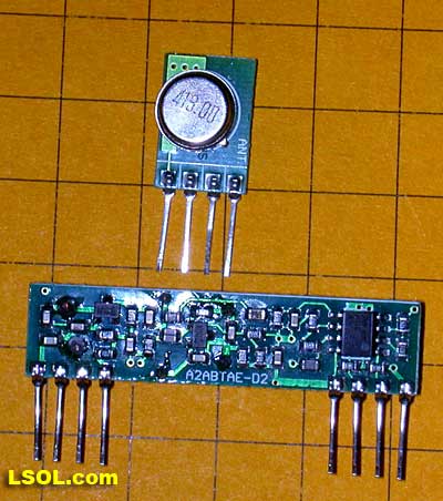
- Using radio frequency based transmitter / receiver units. This is a more expensive option but devices, similar to those inside of a keychain automobile door opener, that can be interfaced directly to microcontrollers, are available and should do the trick! A transmitter / receiver pair is pictured below.
 On-Board Hardware Once the RF transmitter / receiver option was thought out and chosen for implementation the other hardware components had to be considered. The primary hurdle was to design a device that could sense the train's speed, even when moving at a crawl, and reliably report the speed to the track-side display unit. My first prototype used a reed switch that was mounted on a car's truck. The switch was pulsed on/off by a small magnet that was glued to the inside edge of a rotating wheel. The faster the wheel turned the faster the reed switch sent pulses. All the unit had to do was to count pulses for a second or two and transmit this data to the hand held unit for conversion to speed. If this sounds familiar it is the same method utilized by many sound cards to synchronize chuff sounds with movement and other devices that need to know when wheels are rotating.
This simple design worked well when the train was traveling at a G-scale speed of 20 or more miles per hour but failed miserably when the train was moving very slowly. I added a second magnet to the wheel, giving two pulses per revolution, and things improved. I was getting better data at lower speeds but I could see that I needed to add more magnets to the wheel if I wanted to see a more significant improvement at very low speeds. 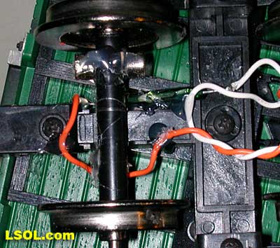
I soon discovered that it was not practical to add more than four magnets so I tried another idea. I made a small brass disk that would fit on one of the truck's axles so that it rotated with the wheels. I cut four slots in the brass disk and placed an infrared LED on one side and an infrared detector on the other side. When the disk rotated the detector saw a pulse of light each time a slot aligned with the LED. The detector sent out a stream of pulses just as the reed switch had done. This method allowed me to cut more and more slots in the wheel, getting finer resolution and better low speed data. Cutting precisely aligned and spaced slots in brass disks soon became tedious and I didn't want to spend as much time creating them as it was taking. I rethought the whole problem and came up with what I consider to be an elegant solution that was both quick and inexpensive to implement. The genesis of the idea was the work I had done on the computer to help with cutting slots in the brass disks. I designed a template in a graphics program and glued it to the brass disks as a guide in cutting. Each of the white lines marked a cut in the brass disk. 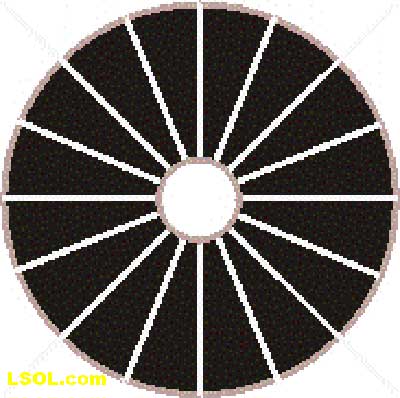
This helped but, as I mentioned above, it was still tedious. The "eureka" moment came when I remembered something that I had done many times in the days before computer data projectors. Remember when speakers stood in front of a group and used overhead projectors and transparencies to display PowerPoint slides? I used them all of the time in my teaching. I frequently printed these transparencies on a laser printer using a special high temperature acetate transparency material. I theorized that I could print the images of the disks in black on clear laser printer transparency material and use those disks to interrupt the light from the LEDs as the wheel turned. (See my article on printing signs using these materials, Color Signs with a Monochrome Laser Printer ) It worked like a charm. This allowed me to use as many as 16 "slots" on the clear, acetate disks. I was finally able to reliably detect train speeds as low as 1 or 2 scale miles-per-hour. That was more like it!
Download PDF - Disk Page 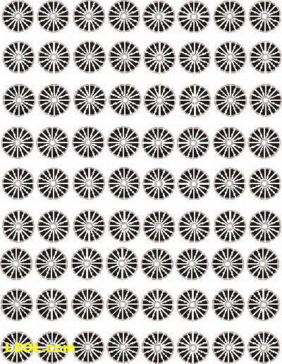 The photo below shows a sheet of acetate printed with the disks. 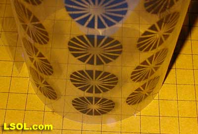
The final design of the sensor used the acetate disk described above and an infrared emitter / detector pair that was aligned between the rotating disk. This design has proven to be very reliable providing accurate and repeatable speed data. The photo below shows my first experimental unit. 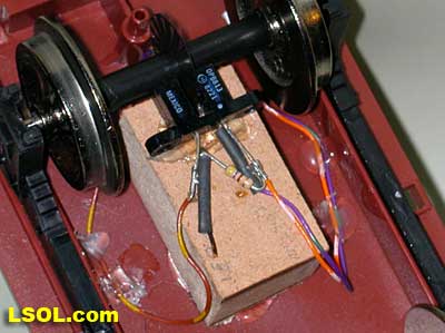
This photo shows the same type of sensor mounted off center to allow the coupler to be installed. 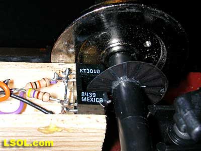 Software Modifications Software Modifications In order to gather data and manage its transmission to the display unit a microcontroller was needed on the on-board unit. This processor connects to the light sensor on the axle and to the RF transmitter. It continuously monitors the sensor and sends of a packet of information, containing the number of pulses in a fixed time, to the receiving unit. Simple, reliable and not very difficult to implement. On the display unit of the speedometer the radio receiver takes the place of the track-side sensors. The software was modified to convert the pulse count that was received from the moving train into speed. Other than that the functionality of the original speedometer remains. Most significantly, it still will work with any scale from 1:1 to 1:220. The biggest difference is that you need to make a separate sensor car to ride on each gauge of track. The only feature that is not implemented is a lap counter as the on-board unit is not currently configured to detect when it completes one circuit of a layout. Something to think about for the future!
The photo below shows the IR emitter detector pair mounted so that the axle of a small Hartland ore car will pass just above it. 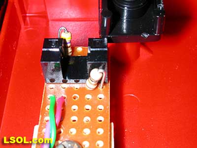 Here you can see the axle and the acetate disk installed so that the disk passes between the infrared emitter detector pair interrupting the passing of the IR as it spins. 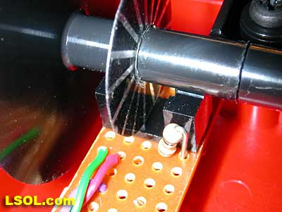
This view is of the inside of the ore car and shows the microcontroller, a PIC16F684, the transmitter module and other parts that make up the onboard components for the wireless speedometer. 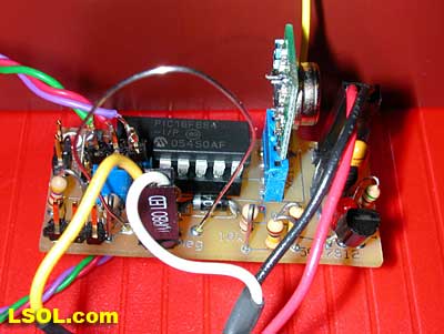 Added Bonuses Not long after I had completed the wireless unit that is described above I decided to convert several of my narrow gauge steam engines to battery power. Since there was very little space inside of the engines I decided to put the batteries, remote control unit, sound card and speaker in a pair of small trailing ore cars. This would allow me to use the same cars with my Shay, Heisler and Climax, quite a savings in hardware compared to adding these items to each engine! In this photo you see the Shay trailed by the sound/RC car (covered with crates of coffee beans), then the speedometer car (covered with barrels of espresso from our new coffee wells) and the battery car (covered with coffee beans from the local coffee mine). 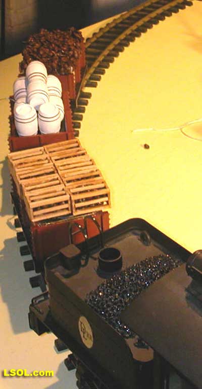
The sound/RC car contains a Locolinc receiver (top), controller (bottom) and a speaker. The sound goes through the crates of beans like there is nothing there! 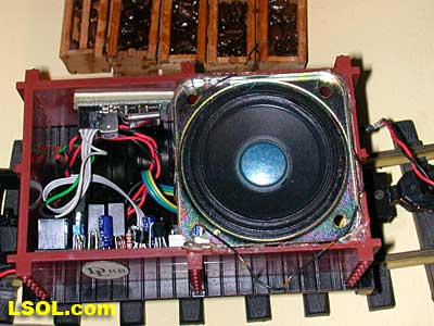 The sound card would not fit inside so it goes onto the bottom of the car along with a reed switch and two "chuff" magnets glued to a wheel (upper right under some hot-melt glue). 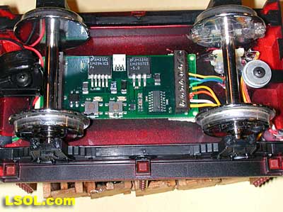
The speedometer car takes power from the battery car and samples the voltage and current being consumed. 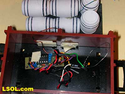 The battery car contains a reconfigured 18 volt NiCad drill battery.  After getting this system working I wondered if I could use the speedometer car to send information other than the train's speed. Since I was working with batteries I thought that battery voltage would be a great place to start experimenting. You may recall that I added a simple circuit, called a voltage divider, to the circuit that controlled the LED Ditch Lights that I wrote about recently. The voltage divider reduces voltages that would damage a microcontroller to manageable levels that can be detected by the microcontroller's analog to digital converter (ADC) circuit. I simply placed the battery car behind the speed transmitter car and ran the battery power through it. I then sampled the voltage, using a voltage divider, and added battery voltage to the data packet that was already sending speed information. Now the display has a continuous voltage readout in addition to the train's speed. This allows me to monitor battery condition and to swap batteries when the NiCads drop below 1 volt per cell. This prevents the cells from reverse charging and being damaged. 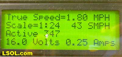
Since the power to the engine from the battery car was already passing through the speedometer car I was able to place a low resistance shunt in series with the battery power. Measuring the voltage drop across the shunt enabled the microcontroller to compute the engine's current draw, another piece of interesting information to include in the data packets and an interesting thing to observe as a train climbs a steep hill. In the photo of the display screen above you can see that the batteries are putting out 16.0 volts and that the engine is drawing only 0.25 amps. This low current value is due to the train going down hill when this photo was snapped. The next upgrade will be a temperature sensor that will be mounted on the engine's motor or battery pack so that its temperature can be monitored. There is really no limit to what the speedometer car can sense and report. I have enjoyed the process of developing this unit and find it a valuable addition to my railway. Visit www.trainelectronics.com. Top of Page
|


