Scenery
Animating Your Layout Part #2
Mar 5, 2008


By David Bodnar
LSOL.com Electronics Editor |
Author
Bio
In Part #1 of our article on "Animating Your Layout" we looked at how to use servos to make things move on your layout. Now lets take a look at how we can put them together using a circuit board to make them work in many different ways.
|
In Part #1 of our article on "Animating Your Layout" we looked at how to use servos to make things move on your layout. Now lets take a look at how we can put them together using a circuit board to make them work in many different ways. Custom Circuit Board Simplifies Things!
In order to make experimentation with servos simpler for me and others I designed a custom circuit board and had a few fabricated. The board is based on the schematic we have been using but has some features that will not be used at this time. Here are four photos of the unit from all angles. If you are interested in using one of these boards please drop me an email
The unused pins in the PICAXE socket are there because the board can also support the PICAXE 14M which has six additional pins. .jpg)
If you look carefully at the photo below you will see that the potentiometer closest to the edge of the board is labeled "Range". The board has a voltage regulator on it (lower right in the photo) so that DC power between 6 and 12 or more volts can be used to power the unit. If you are going to feed it with much more than 12 volts the regulator will get hot and a heat sink may be needed. The programming cable goes to the header in the bottom center.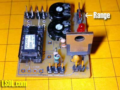
The other pot is clearly labeled "Start" in this photo. The servo connects to the three pin header at the lower right. Its black wire goes to the left onto the pin marked with a "-" symbol. .jpg)
The sound board connects to the pins labeled "Sound". You can also connect an LED, with appropriate current limiting resistor, to the "Sound" pins. The "Trigger" connects to a switch is located in the lower right. The 7805 voltage regulator is clearly visible in the upper left..jpg)
Mechanical Connections
So far the focus of our discussion has been on controlling the rotation of the servo's shaft. Next we have to look at how one can transfer this rotation to make our animation do something interesting. This short video shows the finished outhouse atop its base. The animation starts when a giant hand presses a small button!
In the next video, taken at Phipps, the animation is activated twice. The first activation is because of the train going over the reed switch. The second time a magnet is manually moved across the reed switch. Can you tell it was windy the day this was filmed!!??!! The two photos below show an outhouse that is mounted on top of a plastic utility box that will be buried underneath the outhouse. 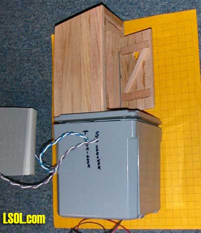 The box, a 4" x 4" x 4" electrical box from Lowes, is waterproof and houses the servo, PICAXE board, sound board and an amplifier from an old PC speaker system The wires exiting the box are for an external speaker, trigger connection that goes to a reed switch on the track and a source of external power. The power wires come in from the bottom through holes that are left unsealed. This allows any water that might get in to escape from the bottom of the box. 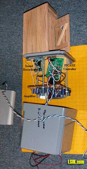
Outhouse Construction
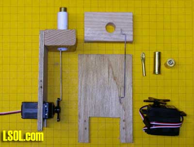
The mechanical connections are very straight forward. The door is opened and closed by a thin piece of piano wire that extends from the door down into the control box. The following set of photos will give you an idea of how it is constructed.The outhouse and servo are both mounted to the top of a plastic box. The servo is screwed to the piece of pine that is just behind it. Note the gasket on the bottom of the lid that helps to make the top of the box water tight. 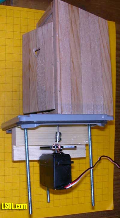 The wire that goes from the servo to the door is bent at both ends. One end goes onto the servo's horn, the other (seen at the right) moves the door. 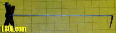
It is much easier to install the wire and pass it through the base if is cut into two pieces that can be reattached after installation. I didn't have a proper fitting to join the pieces back together so I soldered several model airplane wheel locks together. That gave me a sleeve with set screws to attach the pieces of wire together. 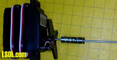 This close up view shows the model airplane hinges that are used to join the outhouse and the door. The rod that connects to the servo can be seen behind the top hinge. 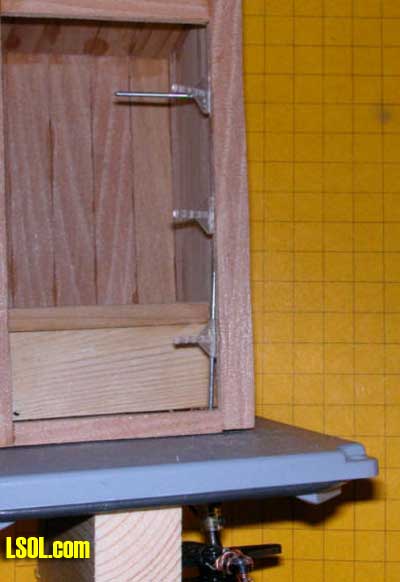 The hinges are inexpensive and make connecting doors a snap. 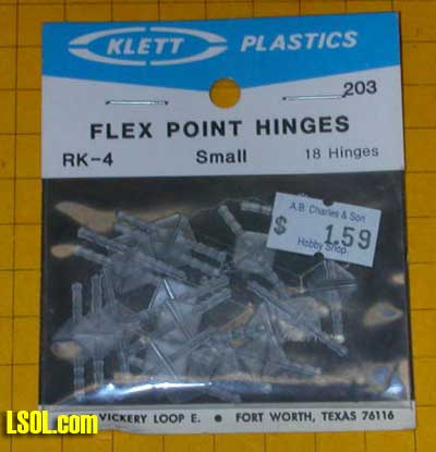
Here the hinges are about half way into the door. When fully inserted and glued they are nearly invisible. 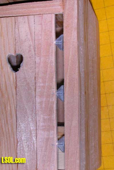 The rod goes into a hole in the top door brace. When the servo rotates the rod the door opens and closes. The coupler makes removing the servo and/or outhouse a simple task. The piece of piano wire at the bottom is connected to the servo's horn with wire and is centered on the servo's shaft. 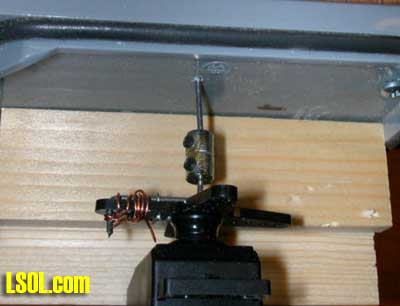
Three bolts attach the amplifier that is seen below the servo. The amplifier was salvaged from an old set of computer speakers and fit in perfectly after a bit of trimming. The loose wires are from the original connections to the speakers and will be redone.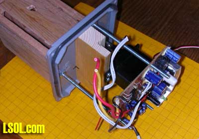
The PICAXE circuit board, on the right, and the sound card, on the left, are mounted high and (hopefully) dry at the top of the unit. Notice that the board used here is not one of the custom boards shown above since this animation was made before the new boards were designed. 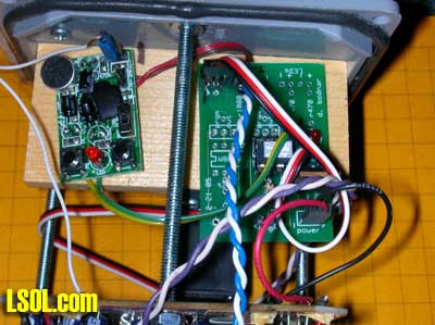 The speaker is mounted externally behind a nearby shed. It is close enough to the outhouse and far enough from visitors so that the sound seems to be coming from the outhouse itself.
Prairie Dog Animation
Each member of the group of animated prairie dogs is operated by an individual servo. The parts that were used to make one prairie dog unit are shown below.The unit on the left is complete. It will be mounted under the lid of a box whose top is flush with the terrain on the layout so that only the small tube shows above ground. A carved and painted prairie dog is placed into the brass tube that is moved up and down by the servo. The parts that were used to make it are on the right and include: - a block of wood with a 1/2" hole in it
- a piece of 1/2" styrene tubing
- a piece of plywood that is notched to fit the servo
- a bent piece of piano wire - there are bends in each end that connect it to the servo and piece of brass tubing
- a spent 357 pistol cartridge that has its primer drilled out to 3/32" - the prairie dog fits into the large opening in the cartridge.
- a 3/32" diameter section of brass tubing flattened at one end and drilled with a 1/16 hole - it will be soldered into the primer hole in the cartridge.
 Here you can see how it is all assembled. 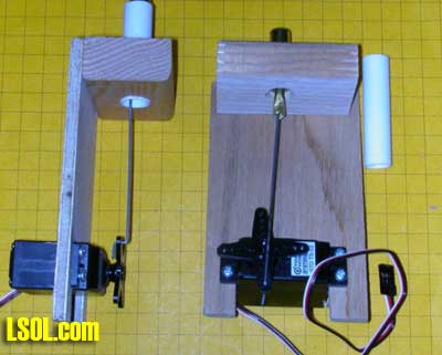 When the servo rotates in a clockwise direction the cartridge goes up lifting the prairie dog that is attached to the cartridge above the ground. When it turns the other way the cartridge is pulled in lowering the prairie dog.
This design, requiring a separate servo and controller for each animated animal, is the third, and most successful, of my experiments. The first used multiple cams, just like in an automobile's valve mechanism, to lift the prairie dogs. A motor turned the cam shaft and springs were used to return them into their holes. The second used a crankshaft, also found in automobile engines. Both designs were rejected for two reasons. First was the amount of power that was required to rotate the cam shaft under the stress of the springs. Even the crankshaft design, that used no springs, needed a powerful motor to keep things humming. The other, and more significant, drawback of both designs was that the prairie dogs always went up and down in the same sequence, just like a car's valves or pistons. There was no variety in movement. Prairie dog behavior dictates that all will be below ground at some time, especially if they are frightened. Neither of these systems provided for that. The servos took care of all of the problems as the sequence of movement wasn't tied to a single piece of hardware but to the computer program that ran the independent servos. Power was no longer an issue as each prairie dog has its own motor. If one failed or faltered the others would keep on working. In this video you can see the prairie dog motor and lift mechanism along with the square wave on the oscilloscope. Any number of animated animals can be controlled by separate PICAXE 08M chips or as many as six can be simultaneously controlled by another of the PICAXE chips that has more pins available.
This video shows a single 18 pin controller operating six servos. The large capacitor, the blue cylindrical object, is needed to keep the system working under the strain of all of the motors being operated at once. A similar system is used with the prairie dogs at Phipps Conservatory. There, of course, the prairie dog's motion is random rather than this choreographed "dance"!
Here you can see the prairie dogs themselves moving up and down on the layout. You will have to look carefully as they are tiny little fellows and blend into the background!
Water Tower Spout Animation
I have added spout movement to several Aristo Craft water towers. In each case the servo was mounted under the floor of the water barrel and a thin stainless steel rod was run to the spout. I made a mock up of such a water spout to show the flexibility and ease of adjustment of the two potentiometer servo circuit that we have been examining. It is shown in the video below. In the interest of time the speed of movement of the spout is fairly fast but could easily be slowed to a more prototypical speed by inserting a longer pause between each servo step in the software. Obviously you would not want to mount the servo below the spout as in this example but it is easily shifted to an out-of-the-way location. Servo Reliability
The question that I am sure has crossed your mind as you read this is:
"How does such a simple device hold up to bad weather and continuous duty?"
I am happy, and somewhat surprised, to be able to report that the prairie dogs and the outhouse have been operating daily at Phipps Conservatory since November 1, 2007. They have not shown any signs of failure nor have problems cropped up over a rather cold and wet Pittsburgh winter. I built backups for both animations in expectation of replacing one or both within a month or two but that has not yet been necessary. Hot summer weather may take its toll but so far, so good!
Other Animation Ideas
As you can imagine there are dozens and dozens of things around a garden railway that can be animated with servos and some simple mechanical linkages. Some of the other things I have used servos for include: - Animating the water spout on a water tower as described above. A sensor next to the track detects when a train comes up to the tower and sits there for more than 20 seconds. Then the spout lowers to the sound of chains and running water. After an appropriate pause the spout returns to its upper position.
- Animating the bucket on a coal tipple. The operation is similar to that of the water spout.
- Lowering and raising crossing gate arms. When a train approaches the arms lower, lights flash and a bell sounds. After the last car passes the arms raise and the sound and lights stop.
- Animating semaphore signals. They can be precisely positioned with servos.
Things that I have considered but not yet done include: - Opening and closing garage doors, barn doors or doors on engine sheds / round houses.
- Raising and lowering flags
- Animating people both on the layout (on a rocking chair, for example) and in or on railroad cars.
- There is no reason why the animation can't be on the train! How about tilting an ore car or opening & closing a box car door?
- Larger servos with more torque could be used to lift and adjust the boom on a crane. You can even remove the stops that limit servos travel and have them rotate continuously with the PICAXE board controlling speed and direction.
I am sure that you have ideas, too! After all, the only limit to what you can do is your imagination! Please let me know your thoughts & ideas and if I can be of assistance. | 
