Scenery
Animating Your Layout Part #1
Feb 27, 2008
By David Bodnar LSOL.com Electronics Editor
Author
Bio
Nothing brings more life to a model railroad layout than bits of animation scattered here and there throughout the landscape. Visitors may not notice the movement at first but will be drawn back to make sure their eyes aren't playing tricks on them! "Did that door just open?" "I could swear that I just saw one of those prairie dogs pop out of his hole!&
Nothing brings more life to a model railroad layout than bits of animation scattered here and there throughout the landscape. Visitors may not notice the movement at first but will be drawn back to make sure their eyes aren't playing tricks on them! "Did that door just open?" "I could swear that I just saw one of those prairie dogs pop out of his hole!"
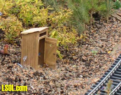
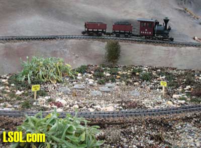
These comments are heard over and over at the new garden railway exhibit at Pittsburgh's Phipps Conservatory. These two simple animations and others add a great deal of interest and realism to the layout. Shortly after the passenger train goes by a secluded farm house a creaking noise is heard as the outhouse door slowly opens. Visitors peer inside to see a cowboy sitting on his throne.
Suddenly he sees that he has an audience and the door slams shut to with a resounding thud! At the opposite end of the layout a family of prairie dogs basks in the sun. An observant eye notes that some of them randomly pop out of their holes and then disappear again. What could cause such a thing to happen?
Servos Provide the Magic Both of these animations are powered by readily available devices that many of us have used over the years in radio control airplanes, cars and boats. These vehicles are commonly controlled by servos, small geared motors that connect to ailerons, elevators, flaps and other steering mechanisms and throttles in radio control systems. Even though animation can be achieved using switch motors, solenoids and other methods I think you will find that servos provide the most repeatable, reliable, flexible, powerful and economical method of moving things on your layout.
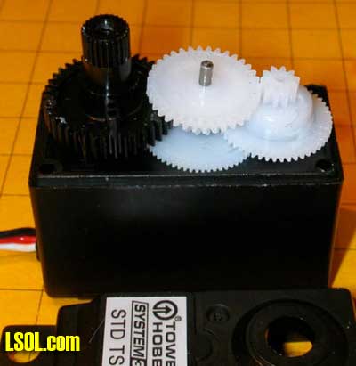
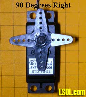
Servo Basics A servo contains a small motor and gear box that rotates a shaft to a precise location and holds it there. This photo shows a typical servo with its top removed.
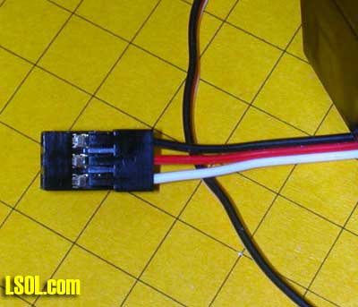
The position of the shaft is based on a digital signal. Most servos rotate through a 180 degree arc while delivering a good bit of torque. Three wires connect the servo to its controller. Two of the wires connect to a source of DC power, normally 5 to 6 volts. The other wire to the servo receives pulses from the controller that tell the servo where to position its shaft. In the photo below the red wire goes to the positive terminal of the power supply, the black wire goes to the negative and the white receives the positioning pulses.
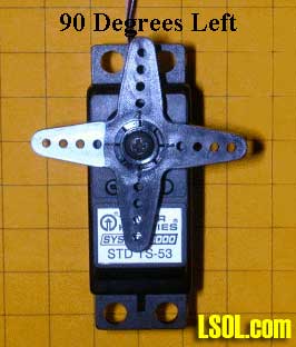
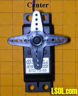
The control pulses are spaced 20 milliseconds apart and the length of each pulse determines where the servo's shaft will come to rest. A 1.5 millisecond pulse will place the shaft in its center position, sometimes referred to as "neutral". A shorter pulse of 1.25 ms will rotate the shaft 90 degrees to the right while a longer pulse of 1.75 ms will rotate the shaft 90 degrees to the left.
In a model airplane radio control system these pulses are generated by the airplane's radio receiver. The length of the pulses is determined by the position of the radio control transmitter's joystick.
This video shows a servo with a digital oscilloscope screen in the background. The square wave on the oscilloscope's screen gives a visual representation of the control pulses. Note that the square wave gets smaller as the servo rotates in a clockwise direction and elongates as the servo rotates counter clockwise.
Click image to activate, then right click and select PLAY to view.
Servo Control We could use radio control transmitters and receivers to control the servos that we use for animation in our layouts but there is a much simpler, more versatile and less expensive alternative. All we need is a device that can deliver an appropriate string of pulses to the servo. This can be done with any number of electronic circuits but the easiest to construct and utilize may be one utilizing the PICAXE microcontroller. I have written a number of articles that describe model railroad applications based on the PICAXE including a Robot Train, Morse Code Beacon Part 1, Morse Code Beacon Part 2, Make Some Working Ditch Lights and a Lighthouse Controller. I encourage you to read these articles for more information on the capabilities of this amazing chip. Please Note: For those of you who would like to experiment with servos and don't want to build your own circuitry or program the microcontroller I have put together a complete unit that is discussed later in this article.
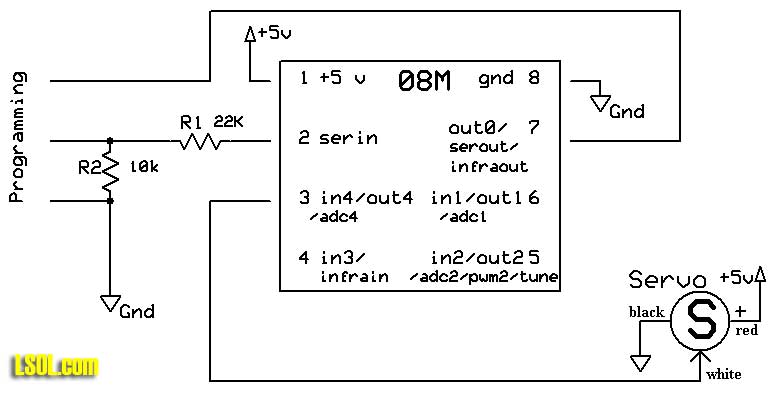
PICAXE Servo Test Circuit The PICAXE circuit that is used to experiment with servos couldn't be much simpler.
Click for Larger Image
Pins 1 and 8 of the PICAXE are connected to a 4.5 to 5.5 volt power supply.
This can be three AA batteries wired in series or a regulated 5 volt supply. In the circuits we are using here I am using the same power supply for the controller and the servo. This works in most cases but some "noisy" servos cause interference and must have their own, separate source of power. Just make sure that the ground connection from both power sources are joined together.
The third wire from the servo goes to pin 3 (also called out4 for output 4). This pin delivers the control pulses to the servo.
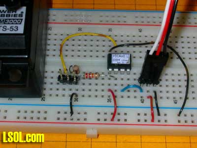
The circuit above is shown in breadboard form below. The servo is to the left and its 3 pin connector is to the right. The 3 pin header between the PICAXE chip and the servo is for programming via the computer's serial port. The two horizontal rows of pins at the bottom are connected to the positive and negative terminals of a 4.5 volt battery pack. Take a moment to confirm that you can identity all of the connections shown in the schematic above as they are made in the photo below.
PICAXE Servo Test Software The software is equally simple as the PICAXE 08M microcontroller has a built in command that can be used to position the servo. The command that we will use is appropriately named "SERVO".
For this exercise we'll just have the PICAXE deliver a range of pulses from one extreme (1.25 ms) to the other (1.75 ms). This will swing the servo's arm all the way from its leftmost position to its rightmost. To set the servo's position the command is SERVO pin, position where "pin" is the pin that connects to the servo's white wire and "position" is a number between 40 and 210. 40 sets the servo at approximately 90 degrees left and 210 places it 90 degrees right. I say approximately because servo manufacturers differ a bit in the servo's range so some experimentation may be in order to set the shaft to an exact position.
Start:
FOR b0=40 TO 210 SERVO 4, b0 PAUSE 100 NEXT b0 PAUSE 1000
FOR b0=210 TO 40 STEP -1 SERVO 4, b0 PAUSE 100 NEXT b0 PAUSE 1000
GOTO Start:
Notes:
"Start" is just a label that marks the beginning of the program
the "FOR-NEXT" loop in the next four lines step through the numbers between 40 and 210 storing the current number in variable "b0"
the "SERVO" command sends the current value stored in "b0" to the servo connected to pin 4
the "PAUSE 100" command slows down the rate of rotation by pausing for 1/10 second (100 ms) between steps
after turning in one direction the program pauses for 1000 ms (1 second)
the second "FOR-NEXT" loop counts backwards "STEP -1" from 210 to 40 and the servo moves back to its original position
after a second 1 second pause the program start over "GOTO Start:"
The program can easily be modified to have the servo move to any position in its range by changing the numbers in the "FOR-NEXT" loop. The speed of movement of the servo is determined by the "PAUSE" command within the loop. The 100 ms pause means that a movement from 40 to 210 will take (210-40)*100 milliseconds or 17,000 milliseconds or 17 seconds. Changing the pause to 10 ms cuts the time to rotate from one extreme to the other to 1.7 seconds.
Using Two Potentiometers to Set Limits For some applications setting the range of motion of the servo within the PICAXE software is the best way to go. There are other times, however, where it is convenient to be able to adjust the rotational limits without modifying the software with a computer.
Click for Larger Image
In the schematic above there are two potentiometers connected to the PICAXE through pin 5 (adc2) and pin 6 (adc1). Examine the wiring of the potentiometers, R5 and R6. Note that both have one end connected to +5 volts with the other end going to ground. The center connection, which is controlled by the shaft on the pot, goes to the PICAXE pin. That pin has a variable voltage between 0 and 5 volts on it depending on the position of the wiper on the pot. The two PICAXE pins that are connected to the pots are called ADC pins, this stands for Analog to Digital Converter. In other words these pins can take a variable analog voltage and convert it to a digital number between 0 and 1023. These numbers can be used to set the upper and lower range of the servo. When the pot is turned towards the 5 volt contact the PICAXE "sees" 5 volts and converts that to the numeric value 1023. When the pot is turned to the end closest to ground the PICAXE "sees" 0 volts and reports that as 0. Positions in between 0 and 5 volts are reported as numbers between 0 and 1023. (If you are wondering why the PICAXE uses what appears to be an unusual range of 0-1023 it is because 1023 is an even number to a computer. Remember that computers "think" in binary, base 2, where 1023 = 1111111111 binary.)
The prototype board below has the two potentiometers added to the right of the PICAXE. The pot on the left sets the counter clockwise starting position. The other pot sets the range of motion.
SYMBOL CCWMax = 200 '225 manual recommended max SYMBOL CWMin = 30 '75 manual recommended min SYMBOL RangeMax = 170 SYMBOL Temp = b0 SYMBOL Range = w5 'max to min range SYMBOL CCW = w6 'where to start rotation SYMBOL CW = b3 SYMBOL Temp2 = b5 SYMBOL Delay = 15 SYMBOL ServoPin = 4 SYMBOL Trigger = pin3
Start: LOW ServoPin 'relax servo 'IF Trigger = 0 THEN Start ' wait till button pressed
GOSUB GetPots: FOR Temp = CCW TO CW Step -1 SERVO ServoPin, Temp PAUSE Delay NEXT Temp
pause 1500
GOSUB GetPots FOR Temp=CW TO CCW Step 1 SERVO ServoPin, Temp PAUSE Delay NEXT Temp PAUSE 1500 GOTO Start:
GetPots: READADC10 2, Range Range=1023-Range Range=Range/6 READADC10 1, CCW CCW=CCW/6 + 30 Temp2=Range+CWMin IF CCW <Temp2 THEN Skipover CW=CCW - Range MIN CWMin GOTO Skipover2
Skipover: CW = CWMIN
Skipover2: RETURN
Notes:
This program uses Symbols to substitute more meaningful words for constants and variables. Thus memory locations W5 and W6 become Range and CCW. The use of symbols in programming the PICAXE is optional but it makes the program's logic clearer and the variables are easier to remember.
Since we will be checking the pot settings twice I put the pot reading section at the bottom as a subroutine that is called by GOSUB GetPots. That command says go to the routine and do what is there. The RETURN command at the bottom of the routine returns to the line after the GOSUB and the program continues.
READADC10 is a command that gets the position of the potentiometer and stores that value in a memory location, either Range or CW. The value returned is between 0 and 1023.
We are using word variables (W5 & W6) for the pot readings. Normal PICAXE variables, B0 or B1 for example, are byte variables and can only store numbers between 0-255. The READADC10 command reads the pot and converts its analog value to a 10 bit number between 0 and 1023, thus a variable that can store a number larger than 255 is needed.
The other commands in the "GetPots" subroutine, Range=Range/6 and CCW=CCW/6 + 30, scale the readings from the potentiometers and adjust them so that their rotation matches the rotation changes that are seen in the servo.
After the potentiometer reading are completed the servo goes to its one extreme position, pauses for a time, 1.5 seconds in this case, then returns to its other position.
Adjusting the Servo Position To adjust the servo turn the potentiometer that is connected to pin in1, CCW in the program, all of the way towards the positive terminal. Turn the other potentiometer, called Range, all of the way towards its negative terminal. This sets the servo to start at its leftmost (most Counter Clock Wise) position and rotate to its maximum range. If the CCW pot is turned to the right the maximum CCW position is moved more to the right. Moving the Range pot to the left decreases how far the servo will move. Adjusting the two pots will give you complete control over the starting and ending point for the servo.
Triggering the Servo The remaining input pin, Pin 4 (also called in3), is used for triggering the servo. It can be connected to any type of normally open SPST switch. For the Phipps layout I triggered the action in the outhouse with a reed switch that closes when a magnet glued to the bottom of the engine passes over it. The switch briefly connects Pin 4 (in3) to + 5 volts. When the switch is released resistor R4 immediately pulls the pin to ground. When a PICAXE pin "sees" + 5 volts it's value is "1". When it is connected to ground and "sees" 0 volts it's value is "0".
Click for Larger Image
The only programming change that is necessary is to remove the apostrophe from the line (about 12 lines down from the top) that reads:
IF Trigger = 0 THEN Start ' wait till button pressed
You may remember that in programming the apostrophe makes the line a remark not a command that will be acted upon. Removing it activates the command. If Trigger = 0 the button is not pressed and the program goes back to the "start" location. When the button is pressed the value of "Trigger", which is just another name for "pin3" becomes a 1 and the program continues. Simple!
Sound with Motion You might think were are completely out of pins on the PICAXE but pin 7 (also called out0) can be asked to do double duty. Under most circumstances pin 7 is connected to the programming cable. It can be used as an output pin as well. The output device is this case is a digital sound card that can be triggered as the servo is activated. I have had very good luck using digital sound recorders from Electronics 123. The unit I use is A96010 which is available for less than $10.00. These and other sound boards are discussed in some detail in another article that deals with sound and model railroads. As you can see in the schematic below the sound recorder module only has a few connections. Power for the unit can be up to 6 volts so it works well with the 5 that we provide for the PICAXE board. Two wires are for a speaker or, in our system, an amplifier that gives much greater volume. The sound starts when a button is pressed or when the PICAXE activates the board through the button's connection.
Click for Larger Image
Notes on the schematic:
Only one wire is needed to connect to the Play button on the sound recorder. The other connection is through the common ground that is shared between the two boards
Since pin 7 (out0) is shared with the programming cable the sound recorder will be activated whenever a new program is loaded.
The amplifier is likely to need more than 5 volts to give adequate volume. That is why 12 volts is specified on the schematic.
If you hear a hum from the amplifier when the servo is running, as I did, put an electrolytic capacitor (I used 680 mfd / 16 volts) across the power leads to the servo.
The only software change is the addition of code to toggle the state of pin Out0 so that the sound is started at the right time. In the example program below the sound is started as soon as the button is pressed. The changes are highlighted in bold type. Even though you might think that the placement of the LOW Audio command is critical as it could stop the sound prematurely, this is not an issue as the sound will start and continue playing to its end no matter when the audio pin's state is changed. Just make sure it is located somewhere in the program where it will be invoked before the sound clip is completed or the sound will start over again.
SYMBOL CCWMax = 200 '225 manual recommended max SYMBOL CWMin = 30 '75 manual recommended min SYMBOL RangeMax = 170 SYMBOL Temp = b0 SYMBOL Range = w5 'max to min range SYMBOL CCW = w6 'where to start rotation SYMBOL CW = b3 SYMBOL Temp2 = b5 SYMBOL Delay = 15 SYMBOL Audio = 0 SYMBOL ServoPin = 4 SYMBOL Trigger = pin3
Start: LOW ServoPin 'relax servo IF Trigger = 0 THEN Start ' wait till button pressed
HIGH Audio GOSUB GetPots: FOR Temp = CCW TO CW Step -1 SERVO ServoPin, Temp PAUSE Delay NEXT Temp
LOW Audio pause 1500
GOSUB GetPots FOR Temp=CW TO CCW Step 1 SERVO ServoPin, Temp PAUSE Delay NEXT Temp PAUSE 1500 GOTO Start:
GetPots: READADC10 2, Range Range=1023-Range Range=Range/6 READADC10 1, CCW CCW=CCW/6 + 30 Temp2=Range+CWMin IF CCW <Temp2 THEN Skipover CW=CCW - Range MIN CWMin GOTO Skipover2
Skipover: CW = CWMIN
Skipover2: RETURN
In part two we will look at how a custom circut board can simplfy things and get a close up look of how to put some animations together.
Updated kit and software information
I have added detailed notes on how to construct the servo kit and some variations on the software to control the servo on my web page. Have a look at:


.jpg)