Power, Sound, R/C
:
Remote Control
Garden Railway Sensors - Part 1
Mar 16, 2005


By David Bodnar
LSOL.com Electronics Editor |
Author
Bio
Adding realism to our garden railway systems involves many things.
|
Adding realism to our garden railway systems involves many things. One of my favorites is to have some event take place when a train approaches a point in the track. This event can be something as simple as turning a light on or off or as complex as having a crossing gate drop to the accompaniment of bells and flashing red lights. To have such things triggered appropriately we must sense the presence of the train as it passes some designated point in its travels.
In this article I would like to explore a number of devices that can be used as sensors on a garden railway and the advantages and disadvantages of each. The objectives that these sensors must meet are simple: 1. They must reliably detect the passing of a train or (if installed on the train) must detect when the train passes a certain point on the track.
2. They must withstand exposure to rain, snow, ice, heat, cold, sunlight, insects and dozens of other environmental conditions.
3. The cost must be reasonable. Mechanical Switches We'll start with a simple event, turning on an LED or other light, as a train passes a crossing. The most straightforward way to turn the light on is to place a small switch, called a micro switch, between the ties in the track so that the bottom of the train pushes down on the switch as it passes and turns the light on. 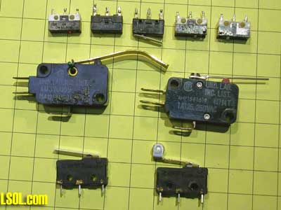
Micro switches are available from a number of sources including Radio Shack (275-016 & 275-017), Hosfelt (51-403) and All Electronics (SMS-209 that claims to be watertight!) You can also salvage very small micro switches from old computer mice. Each of the two or three mouse buttons activates a micro switch that is inside of the case. The smallest switches in the photo above were removed from mice.
There are a number of issues involved in the selection and placement of switches. Since there must be mechanical contact between the train and the switch for it to work you must make sure that whatever part of the switch the train pushes on moves enough to activate the switch but does not provide sufficient resistance to derail lighter cars or scratch finishes. Switches can be placed on the side of the track or under it. Either way you also need to place it so that a train passing in either direction will activate it and will not snag on it. Sidetrack: Let's make sure everyone is on the same page as we talk about switches. There are a number of different ways that mechanical switches can be configured. The simplest is a SPST (single pole / single throw) switch that just connects or breaks the connection between two contact points. Such a switch can be normally open (NO) or normally closed (NC). Its schematic is below. Other common switches are: SPDT (single pole / double throw) one contact (generally called common) can connect with one of two contacts called NO (normally open) or NC (normally closed). Some double throw switches also have a center off position where none of the contacts are connected. DPST (double pole / single throw) two separate contacts can connect with two other contacts can be NO or NC DPDT (double pole / double throw) two separate common contacts can connect with two pairs of other contacts, two NO and two NC 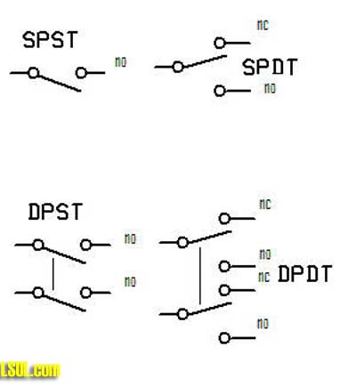 The two SPST switch schematics below are for momentary NO and NC switches. These are spring loaded switches that return to their normal state after being pushed. The two SPST switch schematics below are for momentary NO and NC switches. These are spring loaded switches that return to their normal state after being pushed. 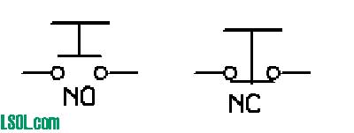
I have had some success with this method by using a micro switch that has a small metal arm attached to it. When the arm is depressed it triggers the switch contacts. If you extend the metal arm by soldering or gluing a longer metal piece of curved metal to it a passing train will push the arm down and turn on the light. If you want to give this type of sensor a try make sure that you select a single pole single throw (SPST) switch this has either normally open (NO) contacts or a single pole double throw (SPDT) switch that has both normally open (NO) and normally closed (NC) contacts as you will connect the LED or lamp to the normally open contacts. If you mount the switch below the train so that it contacts the bottom of the engine or cars be careful to mount it so that the lowest hanging part of the train activates the switch. Here is one method of mounting a micro switch. First extend the switch's arm curving it gently so that a train passing in either direction will activate it. Then cut a section of tie so that the switch can be glued into the notch. 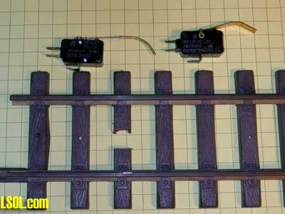
Test fit the switch and adjust it so that it is activated by the lowest part of your engine or rolling stock. Glue the switch to the cut tie and wire it to the circuit. 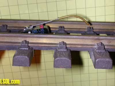
Here is a simple circuit, using a single LED, that can be used to test the NO contacts on the switch 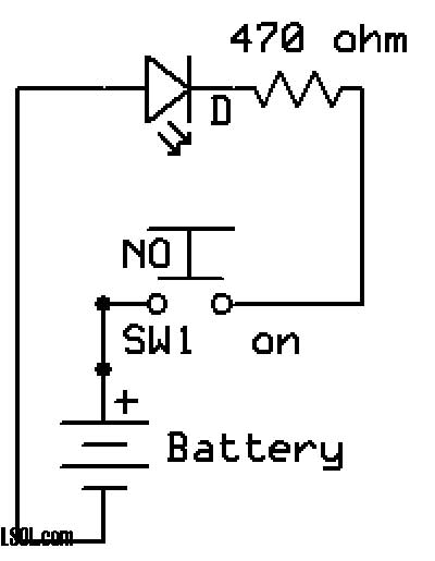
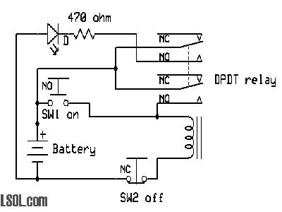
This seems like a simple sensor to implement and it certainly meets at least one of our objectives, it's inexpensive. It is, however, not particularly reliable as the switch and/or its arm can easily be misaligned, fouled by ballast & debris or snagged on the passing train with unfortunate results. It will also flash the light as the switch arm moves up and down in response to the passing of the various parts of the train's underbelly or the sides of cars. In addition, most switches that might be used for this purpose are not designed for outdoor use so they are likely to corrode and fail in short order. I have seen this type of sensor used successfully on indoor layouts but I have had mostly bad experiences when using them outside. If you do get mechanical switches to work properly on your railroad there is a simple circuit with a single relay and two switches that will turn a light on when the first switch is activated and leave it on until the second switch is hit. | Sidetrack: Relays are mechanical devices made up of a coil of wire and a number of switch contacts. They can be found it SPST, SPDT, DPDT and a number of other configurations. A relay changes the switch contacts from one position to another when enough current goes through the coil to create a magnetic field that is sufficient to pull the switch contacts together (for NO contacts) or apart (for NC). Relays are normally rated by the voltage needed to operate them. |
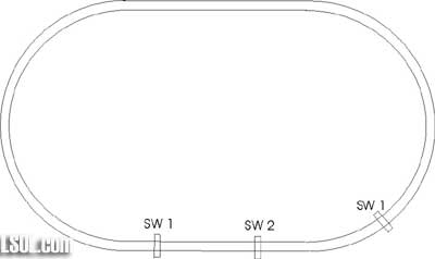
The schematic below should help you to understand how this circuit operates. When the train goes over the first switch (SW1, a NO switch, in the diagram) it connects power to the relay's coil connecting the NO contact with the common center lead. Notice that the two bottom relay contacts are connected in parallel with SW1 and also serve to keep the relay on. When the switch opens after the train passes those contacts keep power flowing to the relay coil and the LED stays on as power to it flows through the second set of contacts.
The second switch (SW2) is a normally closed switch that is wired in series with the power going to the coil. When it is hit by the train its contacts open and power to the coil on the relay is interrupted and the spring in the relay returns the contacts to their normal position and the LED goes out.
To build this circuit start with a DPDT relay that has an operating voltage that is appropriate for your railway. I generally choose 5 volt relays as I can easily make higher voltages into 5 volts but the opposite conversion can be a bit of a challenge. The 5 volt relays I used are from Electronic Goldmine and cost less than $2.00 each. The contacts for the coil are at one of the relay and the switch contacts are grouped into sets of three, one NO, one NC and one Common in each set. The pin connection diagram is frequently printed on the case or you can determine the common, NC and NO contacts with an ohm meter. 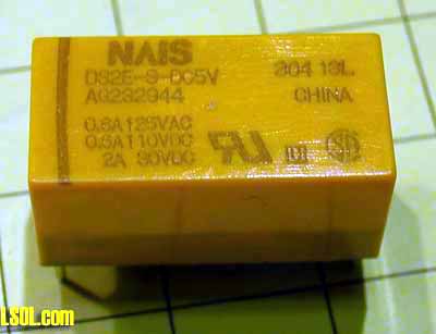
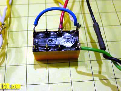
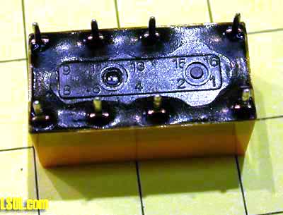 This particular relay (part # G15204 from Electronic Goldmine) has the two contacts for the coil at the far right, labeled 1 and 16. The next two pins (numbered 2 and 15) are the two common terminals for the DPDT contacts. 6 and 11 are the NC contacts and the two at the far left (8 and 9) are the NO contacts.
The two pictures below show wide and close-up views of the test wiring of that relay. The NO switch is on the left wired with yellow and white wire. The NC switch is below wired with black and green. The two wires exiting the photo at the top (red and black) go to the 5 volt power supply. 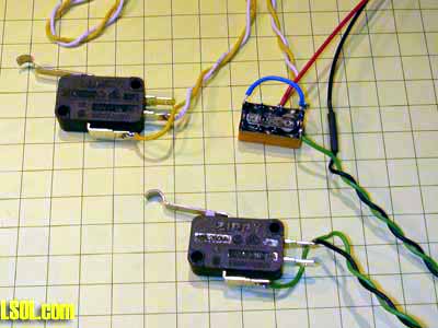 The three terminals (numbered 4, 6 and 8) make up the unused connections that you can use to activate your device. 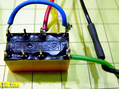 There is one unusual characteristic of this relay that I had not run across before. The coil is polarized. That means that the positive and negative power connections must be made correctly or it will not work. Most relays don't care about polarity. In this case I wired it incorrectly the first time and it did not work. Just reverse the power connections connecting the red, positive wire, to the NC reed switch and the black, negative wire, to pin 15 and it should work just fine. Alternatively you can just order Electronic Goldmine's part # G15205 that has a non polarized coil and you can forget about polarity altogether!
Modifications You will want to modify this circuit a bit if you regularly run your trains in both directions. As set up above a train moving in a clockwise direction, for example, would hit SW1 first, turning on the relay, and then SW2 turning it off. If you ran the train in the other direction the train would hit SW2 first, doing nothing, and then SW1, triggering the event which would continue until the train completed its loop and hit SW2 again. IF we add a second NC switch, wired in series with SW2 and placed a distance away from SW1 in the opposite direction from the first NC switch, the event would stop whenever either of the NC switches was hit. 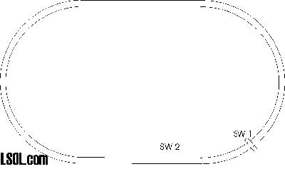
Magnetic Reed Switch A better alternative to mechanical switches that require physical contact between the train and the switch is the magnetic reed switch. Magnetic reed switches are made up of two overlapping strips of ferromagnetic material that are sealed within a glass cylinder. The glass case serves to keep the reeds properly aligned so that they normally do not touch and to protect them from environmental contamination. When a magnetic field from an external magnet comes close to the reeds they assume opposite magnetic polarity and are attracted to each other completing a circuit. Reed switches of this type are almost always normally open (NO) switches. That is, they are open or off under normal conditions and only close and complete a circuit when a magnet comes close to them. 
Reed switches are available from Hosfelt (51-031, 51-260, 51-144), All Electronics (RSW-14) and Electronic Goldmine (G13087). They are not currently available from Radio Shack. When selecting a reed switch for model railroad use I have found that the smaller the reed switch the better as the larger ones seem to require a stronger magnetic field to activate. 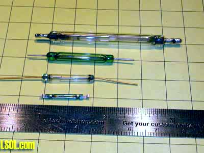
Reed switches are ideally suited to model railroad use, especially when used outside. They are used by both Phoenix and Sierra sound boards to activate bells and/or whistles when a train passes a magnet that is mounted on the track. They also can be used to trigger events on board a train that start when the train moves by using a reed switch on a truck that is turned on by a magnet on the axle that moves by it when the train starts rolling (see details in: Give Your Railroad A Voice - Part I One word of caution when working with reed switches similar to the 3rd one in the photo above, don't try to bend the wires coming out of the glass tube with your fingers! Doing so is almost guaranteed to break the glass. Grip the wire with needle nose pliers next to the glass and then bend the wire as needed. 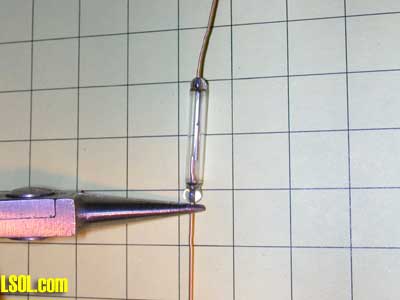
Track side events can also be activated by placing the magnet on the train and the reed switch on the track. As the train passes the switch is activated and the event is triggered. The main drawback to using magnetic switches in this way is that the magnet on the train has a tendency to attract any metal debris that it comes across in its travels. On the plus side, it might pick up a missing metal part!
If you want to use a pair of reed switches to turn a light on at one point and turn it off a bit later as we did with the mechanical switches you are likely to run into one major difficulty. Commonly available reed switches almost always have NO contacts. For our circuit to work we need one NO switch to turn the light on and one NC switch to turn it off. Before you spend too much time looking for NC or SPDT reed switches you should consider turning a standard NO reed switch into a NC. To do this you will need a NO reed switch, a piece of Plexiglas, a small magnet and some glue. 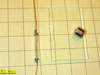
The idea is to glue a small magnet and the reed switch to a base so that the magnet keeps the switch's contacts closed. When another magnet comes close it interacts with the first magnet's field enough to open the contacts back up giving us a NC reed switch! First glue the reed switch to a piece of Plexiglas or other non-metallic base material. I found that the reed switches that I used worked best if the reeds inside of the glass vial were held in a vertical position. Next attach an LED or other light and battery to the reed switch so that you can tell when its contacts are closed. Put the small magnet on the bottom of the Plexiglas and move it around until the reed switch's contacts close and the light goes on. Now bring another magnet near the reed switch and see if the contacts open again. It will probably take a bit of experimentation, and at least 3 hands, but you should be able to find a position for the first magnet so that the reed switch reliably keeps its contacts closed but opens them when a second magnet is nearby. Once you find a location that works well glue the magnet in place. Below are three NC reed switches that I put together while testing. Each of them has a small reed switch on one side of the Plexiglas and a small magnet strategically placed and glued on the other side. 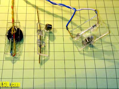
With a NC reed switch you can easily duplicate the circuit we used before by simply substituting reed switches for micro switches. Here are two photos of the test circuit and the two reed switches, one NO and one NC. 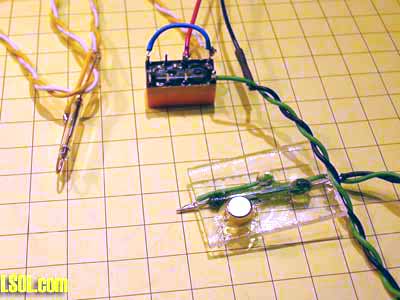
Interfacing with sound boards If you would like to use either the mechanical switches or reed switches to activate any of the sound boards mentioned in the LSOL articles "Give Your Railroad a Voice" here are some notes that may help. 1. Four Train Sound Board #1 - since this sound board generates several seconds of sound from a single button push or reed switch connection all you need to generate that sound is a single NO switch connected to the activation connections for one of the four sounds. You could easily put two reed switches under the track, one to the left and one to the right, and have one connected to one sound, the bell perhaps, and the other connected to the whistle sound. They could be activated by placing magnets to the left or right on an engine or car. 2. Four Train Sound Board #2 (EM-105) - this sound board only creates a brief sound from each button push so it should be used with the relay circuit below. A minor modification gives us: 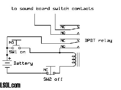
3. Recording sound boards
(See: Give Your Railroad A Voice - Part 2 ) - Dog Bone and RSM units - will play the recorded sound once for each switch closure. If the switch stays closed through the entire playback they will also play once when the switch is released.
- 20 second recorder - if the switch stays closed the sound will repeat over and over until it is opened.
- 120 second recorder - each switch closure will play one message - it will not repeat if kept closed.
Conclusion As you can probably tell I am much more fond of reed switches than mechanical ones for garden railway applications. I think that you will also find that reed switches, especially when you have the capability to modify them to be NC, provide one of the simplest and most reliable methods of sensing train movements and controlling events. In the next part of this article we will examine other sensing options and the advantages and disadvantages of each. Top of Page
|


