Power, Sound, R/C
:
Remote Control
Robot Train Cruise Control
Jun 15, 2005

By David Bodnar
LSOL.com Electronics Editor |
Author
Bio
Picture three or four small engines occupying the same loop of track and keeping a safe distance as they go round and round.
|
Introduction Picture three or four small engines occupying the same loop of track and keeping a safe distance as they go round and round. I am sure that many of us have tried this with radio controlled engines but it can be a constant battle to keep them apart especially if you have many grades to contend with. Now picture the same group of engines automatically keeping their distance from one another, some slowing down as they approach a faster moving train, some speeding up as they are approached from the rear. Combining the pulsed infrared sensor system that was discussed in Part III of my series on garden railway sensors ( Sensors - Part III) and a simple microprocessor makes this a reality.You may recall that pulsed infrared sensors react to a beam of infrared light that is pulsed at 38 kHz. The applications in the article mentioned above were all trackside but there is no reason that the sensor and infrared emitter can't be installed on a moving engine. An interesting and entertaining application of the circuit described above is to place the reflective IR system on the front of a small, fast moving engine that is running on a track behind another, slower moving engine. With this arrangement is it easy for the trailing engine to determine when it approaches the first train and slow its motor to avoid a collision and to maintain a somewhat constant distance. A similar technology, called adaptive cruise control, is currently being offered by several auto manufacturers including Ford and GM. It is a modification to cruise control that is designed to keep an automobile a constant distance behind another car. A recent article by Ralph Walker ( Eggliner Collision-Avoidance System ) dealt with this idea using a commercial IR sensor. Although the system worked there were a number of problems associated with it, including high voltage requirements, large size and its not reacting to an external IR beacon. My version of this system, employing the 38 kHz pulsed IR sensor and a small microprocessor, addresses these problems and has added a stable of rather unique and crowd pleasing engines to my railway.
IR Cruise Control You may recall from the pulsed IR article that an infrared emitter and detector can be placed such that the detector can't directly "see" the IR emitter but will react to reflected IR pulses. This type of placement allows us to put both the emitter and detector in the front of an engine so that the detector responds when IR reflects off of the back of an engine as it approaches it. | NOTE: The following information is for those of you who might be interested in building this circuit from parts. For those of you who that would prefer to work with a completed unit or an engine with this system already installed please see the options available at the end of this article. | The schematic below shows a combination of two of the circuits from the pulsed IR article. The Picaxe 08M microprocessor generates the 38 kHz pulses that are sent to the IR LED, D2. It also monitors the IR receiver and activates the motor control relay when a reflected pulse is detected. The power supply section takes track power and converts it to regulated 5 volts to power the Picaxe. More information on power supplies can be found in my article ( "5 Volt Power for Railway Electronics" ). The optional section (lower right in the schematic) for direction detection will be discussed later. 
Click for larger picture
Controlling the Motor Speed The motor speed is controlled by the relay. One of the motor power connections to track power is cut and is run to the two contacts labeled "to motor". When the relay is open these two contacts are connected and the motor runs at full speed. When the relay is activated on detection of reflected IR the relay contacts close inserting a 20 ohm resistor in series with the motor, slowing it down. When the engine drops back far enough the reflected IR weakens and the relay opens returning the engine to its normal speed. To avoid extremely choppy movements the Picaxe has been programmed to keep the relay closed for at least 1.5 seconds each time it is activated. Note that the value of the speed control resistor will have to be adjusted for different engines. I have used values between 18 and 47 ohms with various engines. Here is a photo of a prototype circuit board that operates as described above. The IR emitter is inside of the black tube at the front of the engine. The detector is just to its right. Behind the sensors are the Picaxe 08M, relay and other supporting circuitry. The 20 ohm resistor is the large gray object in the right rear of the photo. You may note that the resistors used to slow the engine are quite a bit different from the small cylindrical devices that are normally used in electronic circuits. Here we use what are called power resistors because they are able to dissipate several watts of energy when they are placed in series with the engines motor. Placement of the power resistor is also a concern as it has the potential to get very warm, especially if the engine it is slowing is heavy or is pulling a number of cars. 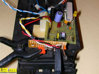
In the close up of the circuit board below the 20 ohm resistor that slows the motor is the rectangular object in the lower right corner. The relay is under it. 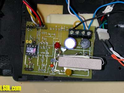
This close up shows the emitter (clear plastic object) and detector (black object to the emitter's right). The potentiometer on the left adjusts the intensity of the IR emitter. Turn it full clockwise to set for minimum power, full counter clockwise for maximum power. Note that the LED power goes through a 200 ohm resistor after the pot so there is no danger of delivering too much current. This part of the circuit is mounted on a separate board so that it can be placed on the front of an engine. Later on you will see how we can separate these two components to facilitate their installation some distance apart in the front of an engine. 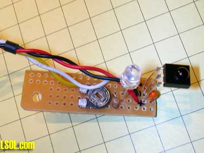
Here is the same board with the emitter inside of an opaque tube so that no direct path for the IR exists between the emitter and detector. 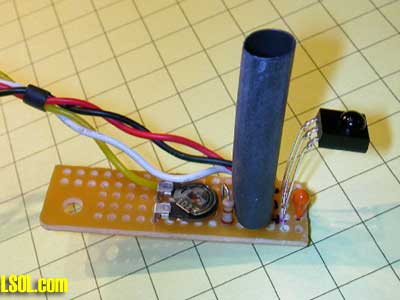
Installation in an Eggliner Aristo-Craft's Eggliner is an excellent candidate for this engine control system. It is easy to disassemble and there is plenty of room inside for circuitry. Start disassembly by removing the 4 screws (two at the top of the photo and two at the bottom) from the bottom of the Eggliner frame. Gently pull off the top exposing a large metal plate that is used to add weight. Remove the two screws that hold the metal weight in place and set it aside. 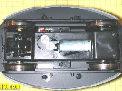
Please note that the location and orientation of the notch in the metal plate that we will need to use to route our connections. 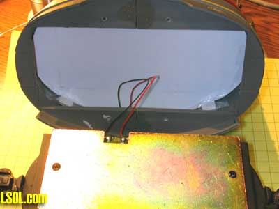
Once the plate is removed you will see a small green circuit board. The red and black wires on the left side connect to the interior lights on the Eggliner. Heat the solder joint where each of these wires connects to the circuit board and remove them. You must also remove the white piece of cardboard that is at the bottom of the Eggliner's body. Some I have worked with are taped in some are attached with hot melt glue. 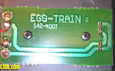
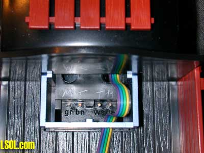
The contacts at the other end of the board connect the track power (the two contacts on the bottom) and motor power (the two outside contacts in the set of three at top).
To give our circuit control over the motor one of these traces needs to be cut. Use a razor blade or Dremel to cut through the trace as you can see in the photo. Several cuts should insure that it is not longer connected. Note the "T" next to the track power contacts and the "M" next to the motor contacts. 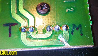
Solder 8" long wires to the track power contacts and to both sides of the cut trace. I soldered a red and a white wire to the two track power connections and a black and a blue wire to either side of the cut. Note that the easiest place to solder the blue wire is to the same contact to which the white wire is soldered. 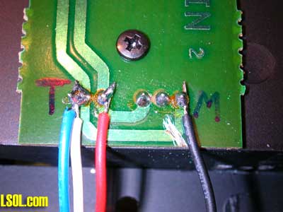
Reattach the metal plate routing the wires over the circuit board, under the metal plate and out through the notch in the metal plate. Next glue a small piece of insulating material (I used a thin 2"x2" piece of wood) to the metal plate and place the circuit board on top of it. Shorten the wires as needed and connect the wires as below. The red and white wires (from track power) go to the two connections on the left and the two from the motor to the two on the right. The large black object is a another type of resistor. This one is 18 ohms, a value that works well with the Eggliner. This power resistor is also placed so that it can easily dissipate heat. 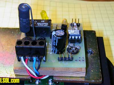
The picture below shows the front of the Eggliner. The infrared LED will be installed in place of he clear headlamp that can be seen at the top of the photo. The infrared detector will be mounted behind a hole that will be drilled in the Aristo Craft Trains label at the bottom of the door. 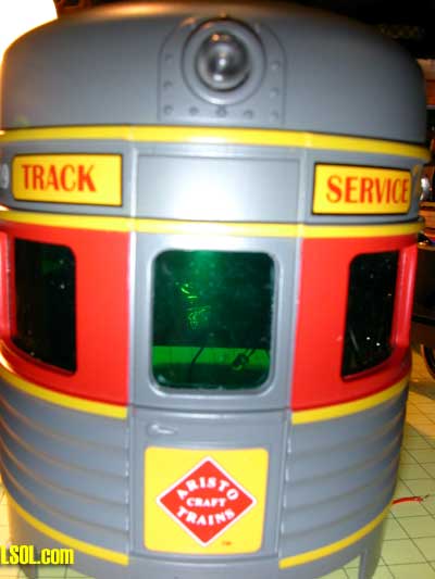
Since the IR LED and detector will be separated by several inches in this installation they are soldered to a wiring harness that will plug directly into the circuit board rather than using the small circuit board mounting method that was shown earlier. You can see that this wiring harness is made up of four wires. The black wire is ground, which goes to the center pin of he IR detector and to the negative terminal of the IR LED. The red wire goes to the right (positive) terminal on the detector. The white wire goes to the left terminal on the detector and the yellow goes to the positive terminal on the IR LED through a 200 ohm resistor that is under the blue heat shrink tubing. The only other component is the 1mfd capacitor that is soldered directly to the positive and negative terminals of the IR detector. Be sure to observe the proper polarity on the capacitor. 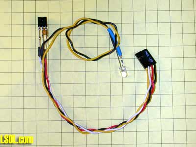
This photo shows the back of the headlamp. It can be removed by chiseling out the hot melt glue that holds it or by pushing the clear lamp housing in from the front. I have done a few of these and the difficulty of removal is a function of the amount of glue that was used when it was put together. Some come out easily, some can't be removed without destroying them! 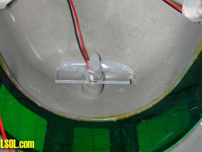
Here the housing has been removed and glued out of the way at the top of the engine. The hole that remains is more than big enough for our IR LED. It can be glued in from the back with hot melt. 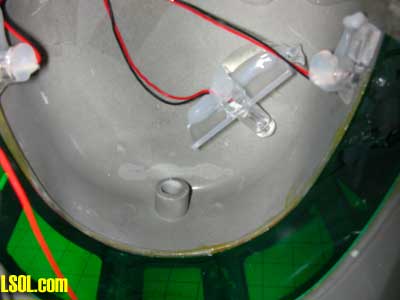
Here is an exterior view of the IR LED. 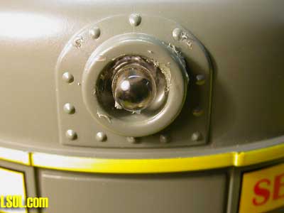
A 3/16" hole in the middle of the bottom of the door will accommodate the infrared detector which is glued in from the rear. Note that the part of the IR detector that you see in the picture is the small round lens that protrudes from the detector. 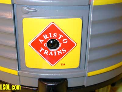
This inside view shows both devices in place. Be careful to add glue to act as a strain relief so that the components are not pulled loose when the Eggliner is apart. Also make sure that the wires attached to the IR detector are glued to one side or straight towards the top of the car so that the black Eggliner base will still fit into the body. 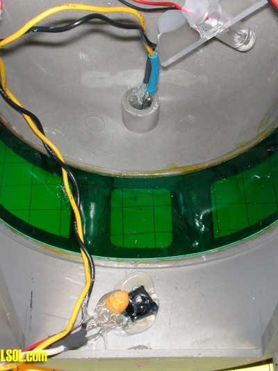
If you would like the lights to flash on or off as the Eggliner slows down it is a simple matter to connect them to track power through the unused half of the DPDT relay. Connect one of the light wires that you disconnected at the start of this installation to one of the track power connections on the controller circuit board. Connect the other wire from the lights to the unused common (marked "com") terminal of the relay. You will note that the unused part of the relay is towards the edge of the circuit board. 
Next decide if you want the lights to go on when the Eggliner slows down or if you want them to be on most of the time and go off only when it brakes. To have them on except while breaking connect a jumper between the other track power terminal the normally closed relay contact (marked "nc"). To have them come on when the car slows down put the jumper to the normally open ("no") connection. The photo above has the lights on most of the time and off when braking. Installation in an LGB Rail Truck Here are some photos that will show you how I added an IR detector and two IR LEDs to a small rail truck. The photo below shows the truck after conversion but before reassembly. Can you find the IR detector and two IR LEDs? The detector is just above the "G" in "LGB" and the two LEDs are below and to the side of each headlamp. 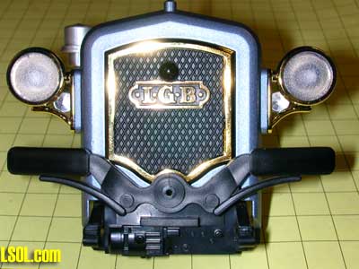
Disassemble the truck by removing the three screws at the rear and pull the frame from the body. Release the tabs behind the radiator to separate it from the body. Remove the radiator frame and drill a 3/16" hole in it as in the photo below. 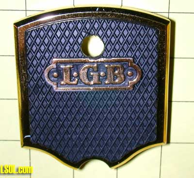
Next cut a hole in the frame just behind the radiator that is large enough to accommodate the body of the IR detector. My Dremel made this easy! 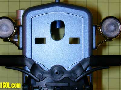
Glue the IR detector to the radiator, bend the leads at a 90 degree angle and reattach it to the frame. The three leads from the detector should protrude into the inside of the body as below. 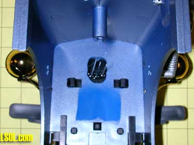
To start installation of the two LEDs drill two very small holes between the first and second louver on each side of the body. In the photo below pieces of wire have been poked through the holes so that they show up more clearly. If you are wondering why I used two LEDs I decided that it would provide a more symmetrical look and the added LED would also produce a greater IR field for the detector to find! 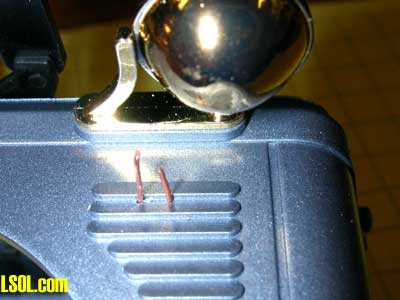
Bend the LED leads at a 90 degree angle and push them through the two holes. 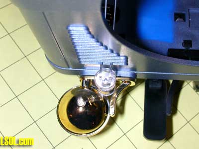
Once through the body bend the positive (longer) LED lead towards the center of the body and the negative lead towards the front. 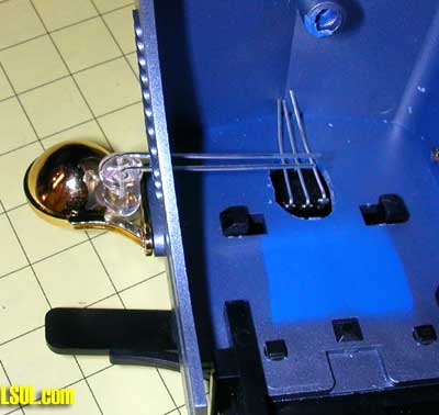
Solder a wire between the center lead of the IR detector (negative lead) and each of the negative LED leads. Next solder a 200 ohm resistor to each positive LED lead. Bring the resistors together as below and solder. Finally solder a 1 mfd tantalum capacitor between the negative and positive leads of the IR detector. 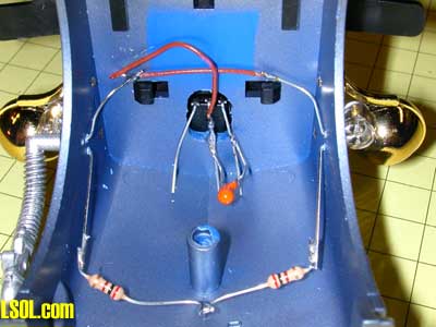
Connect the three wires from the IR detector and the one where the resistors meet to a length of four conductor wire that is long enough to reach to the truck's bed where the circuit board will be placed. I used an old piece of computer ribbon cable for this connection. 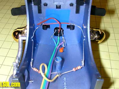
Notch the bottom of the work box that extends into the truck's cab so that the cable can pass through and into the bed. 
Here is the circuit board in the rail truck's bed. All that is left to do is to cover it with a load of lumber, or in my case, coffee beans! 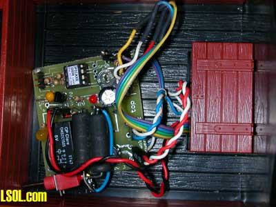
Installation in a Lil'Critter Switcher I don't want to go into great detail on another installation but do want to bring one potential problem to your attention. While experimenting with this system I found that it can be difficult to isolate the IR LED and receiver from one another so that unwanted IR does not reach the receiver. There were a number of times that I thought I had a wiring error because the relay on the circuit board went on and stayed on as soon as power was applied. In every instance I found that the problem was IR finding its way from the emitter to the detector. Thoroughly covering the sides and bottom of the IR LED and the sides of the IR receiver with black tape or some sort of shielding invariably cured the problem. This can become even more of a problem when installing the devices in an engine. Aristocraft's Lil'Critter Diesel Switcher is an excellent candidate for installation as it has two LED lights at the front of the engine that I felt would be ideal for concealing the IR LED emitter and receiver. 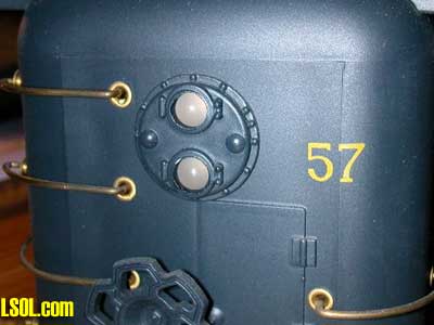
I removed the factory installed lights and the board that supports them and installed the IR LED in one hole so that it protruded from the front of the engine as the other LED had. I installed the IR detector at the rear of the other hole thinking that such a position would shield it from any direct IR emissions from the IR LED. Needless to say it did not work. As soon as the power was applied the relay went on and stayed on. I covered the back of the LED and the back of the detector with black electrical tape and tried again. Same problem. To make a long story short it turns out that enough IR was going through the plastic that separated the two mounting holes to activate the detector. My solution was to remove everything and paint the insides of each hole and the sides and back of the IR LED with several coats of black paint. After that shielding was completed it worked fine! In the photo below the IR LED is at the top and the detector is at the back of the bottom hole. Note the black paint that is visible inside of the holes. 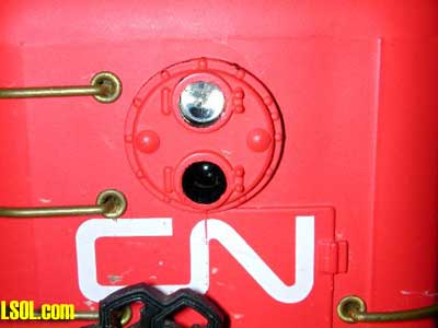
Connecting to Track Power and Motors Even thought every engine might appear to require a different method of accessing track power and the motor, there are really only two different techniques that we need to be concerned with. The simple engines that are ideal for this project usually have a small circuit board, like the Eggliner's, that give access to track power and the motor. Some engines, like the LGB rail truck, have a jumper block that can be removed to gain access to two track power leads and two motor leads. If your motor gets its track power directly from the track all you need to do is cut one of the motor wires and connect the ends to each of the right hand terminals that are labeled "M" for motor. Track power goes to the two terminals on the left. The diagram below shows this connection method which was used on the Eggliner. 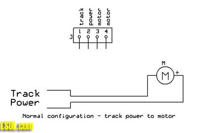
Cut one of the wires to the motor, as we did on the Eggliner's circuit board, and connect the two ends to the motor connections on the connection block. 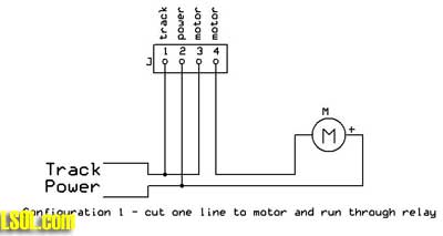
This photo shows another way to connect to track power and a motor via the terminal block. If your motor is not already directly connected to track power, as is the case with the LGB rail truck, give this a try. We still connect both track power wires to the left two track power terminals on the circuit board. You can see that one of the track power terminals two wires going to it. The second wire goes to one of the motor connections. The other connection from the motor goes to the right hand motor connection. Finally a short jumper, yellow in the photo, connects the second track power terminal to the other motor connection. 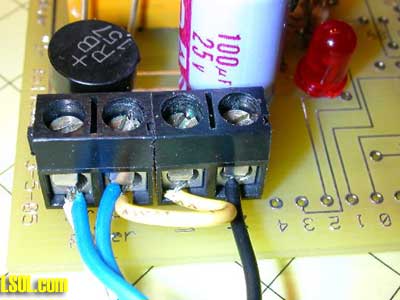
The schematic below may make this more clear. 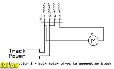
Software for the Picaxe The program to make it all work is below. The comments should make the purpose of each line clear. The only line that you may want to modify is the one that reads "pause 1500". This line makes the engine pause for a minimum of 1.5 seconds any time it detects a reflected IR signal. If you remove it the engine's motion will be very choppy. Increase it if you would like the engine to drop back a greater distance before it returns to its normal speed. symbol irled = 2 'IR LED on pin 2
symbol irsensor = Pin3 'IR Sensor on pin 3
symbol Relay = 1 'Relay on pin 1
main:
pwmout irled, 25, 52 'PWM on for 26 usec period 38.4kHz
pause 3 'pause briefly
if irsensor =0 then goto SawPulse 'IR detected
low Relay 'Relay off
goto skip1: 'skip over IR detected routine
SawPulse:
high Relay 'Relay on
pause 1500 'keep slower speed for 1.5 seconds
skip1:
pwmout irled,00,00 'turn off IR LED
pause 100 'pause 1/10 second
goto main: 'do it again from start
|
Modifications & Enhancements Installing the circuitry and software as described above gives you an engine that will follow behind another engine and automatically slow down whenever it gets within a 10" to 20" of the engine in front of it. If the engine is turned around so that the sensor points backwards it will still slow down when another engine reflects IR onto its detector and cause a collision. This is usually not a good thing! One of the first modifications that I made to this circuit was to add a device that would detect if the engine was running forward or backward. In order to do that I had to be able to determine the polarity of the track power. That is, I needed to know if the left track was positive or negative. I experimented with a few circuits and settled on the one that is shown on the schematic at the beginning of the article. A detail of that schematic is below. 
Here is how it works. The device labeled "optoisolator" is a 6 pin integrated circuit that contains an LED and a phototransistor in a sealed case. The LED is connected to the track power through a diode (D2) and a current limiting resistor (R7). This arrangement will only light the LED when the polarity of the track is set one way. When it is reversed the LED does not light because the diode only allows current to flow in one direction. When the LED in the optoisolator is lit the transistor is turned on and the pin of the Picaxe is switched from low to high. This change allows us to modify the program so that the relay is on, slowing the Eggliner, when it runs in reverse, speeding up when a train approaches it from the rear. (Some of you may note that diode D2 appears to be redundant since the LED is also a diode but I like the extra insurance of isolating the internal diode from track power with D2) The modified program is below. symbol irled = 2
symbol irsensor = Pin3
symbol Relay = 1
symbol direction = Pin4
main:
pwmout irled, 25, 52 'PWM on for 26 usec period 38.4kHz
pause 3
if irsensor =0 then goto SawPulse
if pin4=1 then lr1: 'if direction is forward
high relay
goto skip1:
lr1:
low Relay ' Relay off
goto skip1:
SawPulse:
if pin4=1 then hr1: 'if direction is forward
low relay
goto skip2:
hr1:
high Relay ' Relay on
skip2:
pwmout irled, 00,00
skip1:
pwmout irled,00,00 'turn off PWM
pause 100
goto main
|
External IR Beacon This photo shows the IR beacon that can be used at the rear of a car being pursued by the IR follower. Such an arrangement will increase the distance between the first train and the follower since a much more direct and intense IR beam is emitted by this beacon. The clear LED on the right is the IR unit. The red LED is just there to flash on and off so that you know it is working and to simulate the red beacon that is used on the last car of some trains. With the beacon on a car in front I generally have the trailing car detect it from a distance of 8 or more feet. 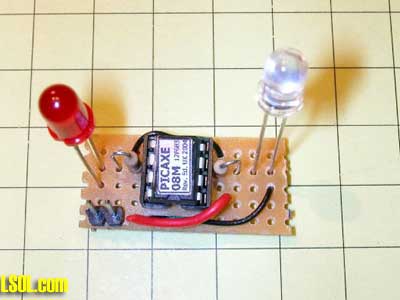
Here is the (extremely simple!) schematic. Note that there are no provisions for programming the Picaxe in this diagram. To keep things small they have been omitted. Just program the beacon's Picaxe using the other board and transfer it to the beacon board when done. 
This circuit does not use a voltage regulator so you must take several precautions with it. First it MUST NOT be powered by more than 3 or 4 AA or AAA cells (voltage between 4.5 and 6 volts) and you must make sure the positive terminal of the battery supply is connected to the right hand terminal, next to the red wire. Reversing polarity even for an instant is sure to kill the Picaxe. This photo shows 3 AAA cells wired in series to power the beacon. 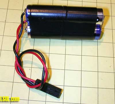
Here is the beacon attached to the back of another railcar with double sided foam tape. The battery pack is visible behind it. 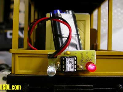
The program for the Picaxe is just a section of the main program as all it needs to do is generate the 38 kHz pulses and flash the red LED. | rem sends 38 kHz pulse to trailing car with IR sensor symbol irled = 2
symbol LED = 1
main:
high LED 'turn on RED LED
pwmout irled, 25, 52 'PWM on for 26 usec period 38.4kHz
pause 3
pause 300
low LED 'RED LED off
pwmout irled, 0, 0 'turn PWM off for a short time
pause 300
goto main: 'do it again! |
Adding Sound or ??? In the Eggliner modification we used half of the DPDT relay to power on the interior lights whenever the Eggliner was running at normal speed. Because the relay contacts can be used to turn just about any device on or off it is easy to use them to add a sound (perhaps screeching brakes?) whenever the Eggliner slows. Just use one of the sound recording devices described in my recent articles connecting the on/off switch to the relay. This is exactly what I have done with my Lil'Critter installation and it works very nicely. Please consider adding one or more of these entertaining engines to your collection. They are great fun. And, as always, let me know if I can help. | Parts list: IR Cruise Control Board - Picaxe 08M microprocessor - www.PHAnderson.com , www.picaxe.com , author (see note below)
- 1.0 uF Tantalum capacitor - Radio Shack 272-1434
- 470 ohm resistor - Radio Shack 271-1317
- 220 ohm resistor - Radio Shack 271-1313 (can be used in place of the 180 shown in the article)
- 1 K ohm resistor - Radio Shack 271-1321
- 10 K ohm resistor - Radio Shack 271-1126
- 22 K ohm resistor - Radio Shack 271-1339
- 1 K ohm trimmer potentiometer - Radio Shack 271-280
- IR LED - Radio Shack 276-143
- red LED - Radio Shack 286-041
- IR Receiver - Glitchbuster PNA4602M (note: Radio Shack 276-640 should work but I have not tested it)
- 2N2222 transistor - Radio Shack 276-2009
- diode - Radio Shack 276-1102
- bridge rectifier - Radio Shack 276-1152
- 5 volt 7805 voltage regulator - Radio Shack 276-1770
- 220 mfd, 35 volt filter capacitor - Radio Shack 276-1017
- 5 volt relay - Electronics Goldmine G15205
Miscellaneous - Circuit board - either from author, see below, or Radio Shack 276-150
- Solder
- Hook up wire
- Hot melt glue
|
The following items are available from the author: Completed and tested circuit ready to be installed in your engine. Please contact the author before ordering so that the appropriate wiring harness for the IR devices and engine slowing resistors can be determined. $85.00 + shipping Complete kit of parts including the circuit board, all resistors, capacitors, sockets, relay, diodes, LEDs, programmed Picaxe, voltage regulator, bridge rectifier and the other parts that are needed to make the complete circuit. You will need to provide a suitable engine, hook up wire, solder, etc. Please contact the author before ordering so that the appropriate engine slowing resistors can be determined. $60.00 + shipping Circuit board only. $15.00 + shipping Programmed Picaxe only. $6.00 + shipping (specify which of the programs in the article you want on the Picaxe) Complete Eggliner installation including a new Eggliner with the wired and tested circuit installed. $125.00 + Eggliner + shipping Complete IR beacon, wired and tested. $20.00 + shipping I have given Radio Shack part numbers for the parts used in this article but you are likely to find much better prices from other vendors, including Hosfelt ( www.hosfelt.com ), Digikey ( www.digikey.com ), Jameco ( www.jameco.com ) - I have links to these and other vendors on my web page at www.davebodnar.com . Top of Page
|


