Power, Sound, R/C
:
Remote Control
Eggliner Collision-Avoidance System
Mar 9, 2005


By Ralph Walker |
Author
Bio
Here is a simple implementation of one of these ideas. It requires only the most basic familiarity with electronics, wiring, soldering and testing.
|
I have a lot of ideas for electronic gadgets which I would buy for my railroad, if they were available. Unfortunately my electronic knowledge is limited. Here is a simple implementation of one of these ideas. It requires only the most basic familiarity with electronics, wiring, soldering and testing. Imagine an analog layout where trains can be placed all over the tracks, with no worries about collisions. Fast and slow trains could co-exist. Robotic controls of the simplest form would replace expensive and complex systems. The resulting system would not be prototypical, but would be great fun and perfect for public displays or garden railroads.  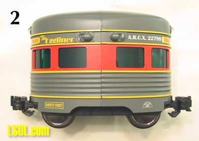
For my proof of concept I combined an Aristo-Craft(tm) Eggliner (tm) locomotive, with a Banner (tm) Valu-Beam (tm) model SMW915D infrared, weatherproof, selfcontained sensor with electromechanical relay output. 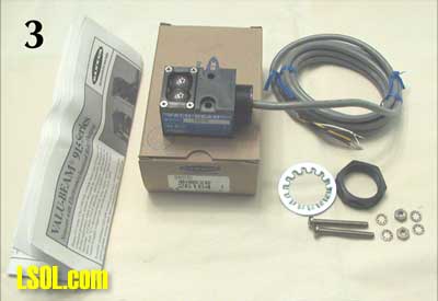 These modules would typically be found in industrial applications, such as monitoring a conveyor belt. The list price for these can be close to $100 but many different Valu-Beam sensors can be had on eBay in new condition for $10. This project involves mounting the sensor inside the Eggliner in such a way that it can look forward. When it approaches a slower train (most trains are slower) the sensor interrupts current to the motor until the slower train pulls ahead. To prevent the Eggliner from stopping completely when it sees another train, I implemented a suggestion from David Bodnar which allows the loco to run at half speed during these times.
There are drawbacks to my design and they are all listed at the end of this article, but the project is easy and does work. Follow these instructions, referring to the illustration numbers in parentheses. 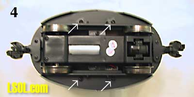 Remove and save 4 screws on bottom of Eggliner - (see arrows). 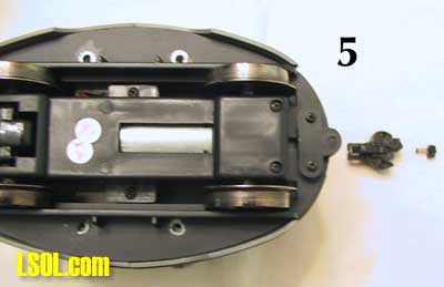 Remove and discard coupler on end shown. This will be the front of the loco. Re-attach the retaining plate for no particular reason.
(You don't have to remove the coupler -- it just makes it easier to see which way the Eggliner is facing). 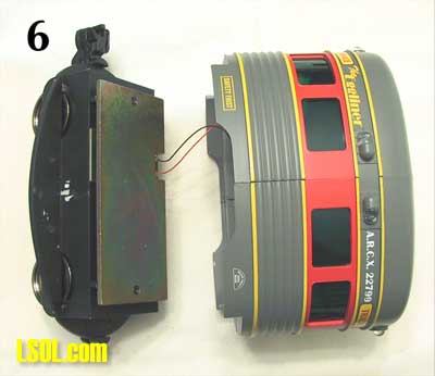 Wrestle the body away from the chassis. 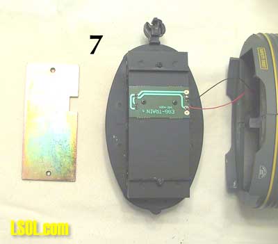 Remove and discard the weight plate, exposing the 'circuit board' which, in fact, contains no electronics.
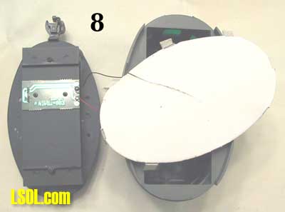 Remove and discard the cardboard floor in the Eggliner body. 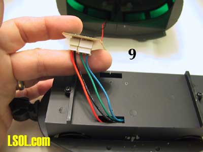 Remove 2 screws holding the circuit board to the chassis. Withdraw the wiring harness, exposing the red, black, green and blue wires. Red and black are track power. Green and blue are the motor wires. Green is connected to black track power and blue to red track power. Just clip all the wires and discard the circuit board and the two connectors. At this point I recommend that you remove the motor block (2 screws) and the rear coupler as some of the following steps are easier without these components installed.
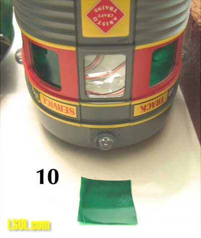 Remove the window at the front of the loco (the end with no coupler), from the inside, using your X-acto knife. The sensor will not work through a window. 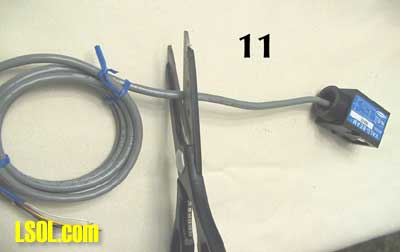 Cut the sensor cable, leaving 6 inches.
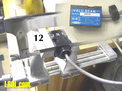 Carefully hacksaw the threaded connector on the sensor. The sensor will not fit in the loco without this step. 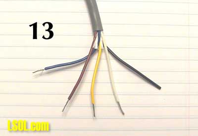 Remove at least 2 inches of the cable outer sheath. If you wish, remove the entire sheath (my choice). Strip all wires. 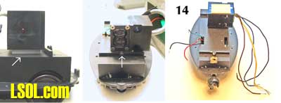 Using THICK (1/8 inch or more) self-stick tape, mount sensor as shown, centering sensor windows over the screw - (see arrows). Now it is obvious why you hack-sawed the threads off the sensor . . . and the point of the thick tape is to elevate the sensor to align vertically with the Eggliner's front window. When you eventually replace the body it is a tight fit but will not be a problem if you have properly centered the sensor.
At this point it is time to tackle the lighting of the body. There are 6 white running lights, no headlight, no directionality and no voltage regulation for these lights. To light the car you simply connect the red and black wires to track voltage. I chose to add a 'brake light', even though no train actually has one. When the sensor sees a train ahead, its SPDT relay turns OFF track current to the motor but the other half of the relay can turn ON an accessory at the same time. So I mounted a 12V red snap-in Radio Shack(tm) indicator lamp (part 272-332, $2.29/ pkg. of 2) 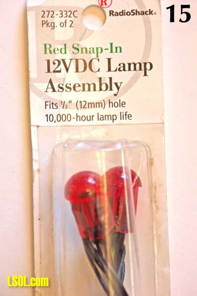 on the rear of the Eggliner and wired it to the relay. Now it is obvious when the sensor has been activated, it makes it a little easier to adjust the sensitivity for smooth running and it looks great. You could wire anything you want into the relay at this point, including a sound module to make the sound of brakes.
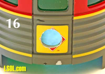 First, drill a 1/2" hole (carefully, in many steps) at the location in the photo. 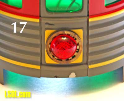 Attach either a few washers or an o-ring to the outside of the lamp. It is best to prevent the lamp from entering the loco's interior all the way, because there is an interference problem with the chassis.
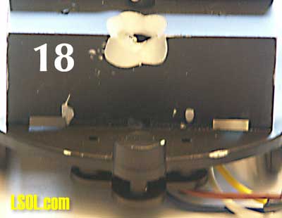 Using your drill, grinder, file or soldering gun, make a notch in the chassis as shown to allow the lamp base to clear and the chassis to be fully inserted. This is the step where it is awkward to have the motor block or the rear coupler in place. Of course if you don't plan to install a 'brake light' there is no advantage to removing these 2 components. The lighting wires are too short and too flimsy, so solder some extensions to these wires. You may wish to slip a piece of heat shrink tubing over these 4 wires and fix them to the interior of the body, to cut down the clutter. You will probably be removing the body several times during debugging and adjustment. 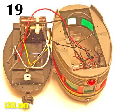 You now have 4 wires from the Eggliner, 5 wires from the sensor and 4 wires from the body. One more component needs to be added and you can solder the whole mess together. As mentioned above, it is necessary to provide reduced voltage to the motor whenever the sensor detects a train ahead. I have installed a resistor which provides an alternate path for the current and is always 'on'. I wanted a resistor which would reduce the voltage by half, and settled on one of 43.5 Ohms. The higher the value of the resistor, the slower the Eggliner will go during these periods. There is no right size resistor and your application might require a larger or smaller value, but 43.5 Ohms is a good starting point. (There is more on this at the end of the article). Be sure you can readily replace the resistor if you don't like the performance.
My tests showed that the resistor could get pretty warm if the Eggliner was constantly slowing down, so I used a large, wire-wound resistor. You might be able to get by with a carbon resistor of 1W or 2W, but there is plenty of room to install a big one. I mounted another piece of self-stick tape on top of the sensor, placed the resistor on top and then used the handy mounting hole in the sensor to run a wire tie around the resistor. If you removed the motor block and rear coupler, re-install them now, fishing the 4 wires up through the floor as shown. 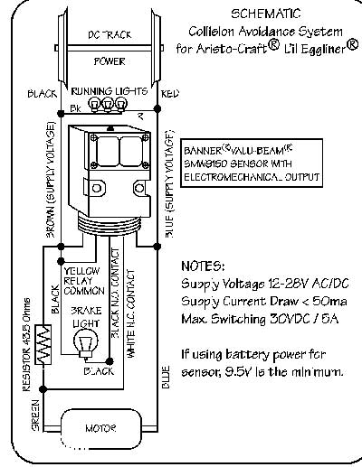 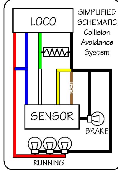
Now you've got to attach the 13 wires that are hanging out of the body and the chassis, along with the 2 terminals on the resistor. Follow the wiring diagrams above to solder the appropriate wires to each other, using your favorite wiring and insulating techniques. 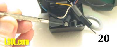 There is a sensitivity or 'gain' adjustment at the back of the sensor. Turn it clockwise until it stops (highest sensitivity). Then back it off exactly 1/2 turn. Re-assemble the Eggliner but do not put the 4 screws back in just yet. You may need to adjust the sensitivity several times. You might consider making a neat little hole in the window at the back of the Eggliner so you could adjust the sensitivity without removing the body. I considered this and realized it would be very difficult to find the adjustment screw through such a hole, so rejected the idea. Then I thought of gluing a tube to the sensor to guide a screwdriver and rejected this idea too. In the end I opted to just leave off the 4 screws holding the body to the chassis and remove the body to make my adjustments.
Operation: Place the Eggliner on a track by inself. The collision-avoidance system will not be activated until DC voltage reaches 9.5v so crank up the throttle. If it goes all the way around the track without hesitation, the sensitivity is adjusted low enough that it does not 'see' objects on adjacent tracks, buildings, etc. Next, hold you hand in front of the speeding loco. It should slow just before hitting you. And when you remove your hand it should continue at full speed. If it does not do so, then track power probably isn't reaching the sensor, so check your soldering. If you have not elected to install a 'brake light' you can observe the red diagnostic LED on the body of the sensor, which lights to indicate operation, but this requires that you cut the 2 wires to the running lights and remove the body. Next, place the loco behind one of your other trains and turn them loose. The Eggliner should race up behind, then slow down at some point between 6" and 3' behind the other train, allowing the slower train to pull ahead. You may wish to watch the video of this action.
ADJUSTMENT: Many factors affect the operating characteristics of this system: ? If the Eggliner sees objects or walls it will slow down briefly. ? The reflectivity of the train ahead will affect how soon the Eggliner sees it. The design distance of the sensor is 30". ? The size of the resistor you chose will determine the speed at which the Eggliner runs when in 'slow' mode. If the Eggliner itself is getting rear-ended, consider reducing the sensitivity or installing a resistor with a lower value. ? If you try to run the Eggliner on a track with a train of similar speed characteristics which is not inself equipped with this system, your Eggliner will be rear-ended. ? There may be trains that are so slow that the Eggliner will still rear-end them even in 'slow' mode. Your choices are to use a larger-value resistor, to avoid placing these 2 trains on the same track or to pull some cars behind the Eggliner to slow it down. You may wish to purchase a white bicycle or truck reflector and hang it on the last car of the train that the Eggliner is following. The sensor will be effective at a greater distance with the sensitivity adjusted lower, eliminating false stops when some other object comes into view. The Banner company actually sells these reflectors for this purpose, but so do Wal- Mart and your auto parts store. If you do use a reflector, the Eggliner will maintain the same distance from whatever train is ahead without regard to its reflectivity. Also you can reduce the sensitivity and thus avoid false hits from trackside objects. I find that a white reflector works marginally better than red. You may also wish to make a 'reflector car' and permanently mount a refleector (self-stick?) on it. Then you could just pull it at the end of any train.
DEFICIENCIES: Here are some areas of my execution that need further development. ? This model sensor requires at least 9.5v, below which the collision-avoidance feature is disabled. There certainly is room for a battery pack to drive the sensor. On my layout I can go pretty slow before the sensor cuts out. You can add a battery pack if your performance is unacceptable with track power. ? Using this sensor requires plenty of space in the front of the locomotive. The functions of this sensor could be duplicated for $10 in a small package utilizing fiber optic emitter and receiver. This package could be placed anywhere, including the tender, and the fiber optics could run to any handy spot in the front of the loco. I chose the Eggliner just because it has a huge cavity for the electronics and has windows of the correct size for the Banner sensor. ? The loco runs at only 2 speeds, so operation is jerky. There is room for improvement here, either by using 2 sensors set to different sensitivities (to achieve 3 speeds) or by some sort of dampening system, but designing this is beyond my capabilities. ? This is a DC-only scheme. I have no idea how well, if at all, the sensor will perform with pulse width modulation. PWM might be the answer to achieving the recommended 12VDC for the sensor.
FINAL THOUGHTS: Go to the Banner website and download their PDF document on the 915 series of Valu-Beam sensors ( www.bannerengineering.com ). There are sensors with different ranges, wavelengths, input voltages, configurations, etc. You could easily incorporate other models of sensors into trackside controls. Initially I thought I could extend the range of the sensor by equipping the leading train with a little infrared LED of the correct wavelength (880mm), but that does not work. These sensors modulate the light and only recognize modulated light of the same frequency. In fact, I could not even get a sensor to recognize the emissions of another identical sensor, so it is possible that the receptor is synchronized to the emitter. Since these devices are used in industrial environments, possibly in a room full of sensors, they are meant to be immune to light from sources other than themselves. More can be done to my simple Eggliner design also. You could even put a sensor at each end and have the Eggliner reverse direction and speed toward an oncoming train, It would be a crowd-pleaser, whether or not it stopped in time. If a collision was imminent a sensor could short out the tracks, shutting down all the trains. I'm sure you will have other ideas. Of course, you could forget my idea of collision-avoidance and use the Eggliner's generous interior and handy window configuration to house a video camera. . . . You may find it easier to following this alternate wiring diagram when soldering the wires together: Top of Page
|


