When I was testing the capacitors and thermistors that were the focus of two recent articles I had a need for a simple controller that would automatically reverse a small engine that was running on a point-to-point track.
Even though I had made up a very nice auto-reverse unit, complete with an LCD display and lots of features, for my holiday incline project I wanted something simpler that would only do the basic reversing of an engine that I needed for testing.
This led me to develop an extremely simple unit that contained only a few parts.
- A DPDT (double-pole-double-throw) relay that would be wired to reverse power to the track
- A transistor to activate the relay
- A diode to protect the transistor from the voltage spike that relay coils generate
Pausing between reversals and control of the relay was done with a Picaxe 08M microprocessor. It was programmed to:
- pause for 60 seconds
- activate the relay
- pause for another 60 seconds
- release the relay
- repeat
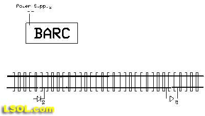
Diodes were inserted in cut sections of track at each end of the point-to-point layout that would bring the train to a complete stop when it passed beyond them. See page 8 of my recent article on Thermistors for details on how this is done.
This simple program did the trick and made my work with the capacitors and thermistors (see: Give Your Engines the Capacity to Ignore Dirty Track and Thermistors, the Magic Behind Smooth Acceleration ) much more efficient.
The simplified schematic is below and shows the minimal circuitry that was needed to make it all happen.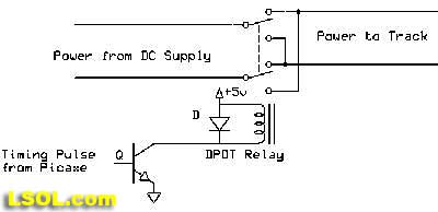
Additional Features
After completing my work with the capacitors and thermistors I revisited this simple auto reverse circuit. Many LSOL members had sent me emails asking that I explain in more detail what I had done and I wanted to clean it up a bit before writing about it. As I mulled this over I began to think about features that I might want to add.
My "wish list" included:
- a method to adjust the delay time other than reprogramming the microprocessor for each time change
- a display to show the time setting
- a display to show the amount of time remaining before the unit reversed the power
- an option to make the time between reversals random
- additional circuitry to make the engine accelerate and decelerate slowly at each end of the track
- a display to show the number of "laps" that the point-to-point train had run
- a way to identify when the train was nearing the end of the track so that deceleration could begin
- the capacity to operate onboard a battery operated train
All this and I wanted to keep the parts count down so that I could make completed units available at a reasonable cost! Not an easy task but a place to start. The next step was to make some compromises. The first was to limit the power output capability of the unit. The design uses inexpensive parts that can reliably supply up to 1 amp at up to 24 volts. This is sufficient for most small engines or trolleys as long as they are not pulling long strings of cars or climbing steep inclines. (See note at the end of the article about a simple modification that significantly increases power capacity.) Another place to balance features and cost is the display. LCD displays, such as those that I use in the train speedometer (see: Is Your Train Speeding? Large Scale Speedometer ) are very nice but can double the cost of a circuit. Not only does the display itself add to the cost but the microprocessor and other circuitry to support it is also more expensive.
LEDs to the Rescue!
Rather than use the LCD display I felt that I could use a few LEDs to give much of the information that I wanted to provide. Since users would not need to consult the display too often once the unit was working that seemed to be an acceptable compromise.
I began to experiment with LEDs and settled on using 3 of them to show the time settings, laps completed and other numeric information. I wanted to be able to display numbers at least in the hundreds. I could use one of the LEDs to represent 1's, another to represent 10's and the third to represent 100's. If I wanted to show a time of 248 seconds I would have the 100's LED flash twice, the 10's LED flash 4 times and the 1's LED flash 8 times. This is certainly not as easy as seeing "248 seconds" displayed on an LCD display but I tried it out and it worked nicely! In the video below the counter counts down from 176 to 154 seconds. Note that it does not show every second as it takes more than one second to flash out most numbers. The sequence in the video is: 176, 172, 167, 163, 158, 154 with the top LED showing 100's, the middle one 10's and the bottom one 1's.
An additional LED would show if the random time option was set.
Changing Settings Once the four LED display design was decided upon and tested successfully I began to think about the controls that the unit would need to set such things as delay time, train speed and the random time option.
Most of us are used to turning a variable resistor (potentiometer or pot) to adjust things. The volume control on a stereo or radio is an example of using a potentiometer to increase or decrease a setting. Most microprocessors have the ability to read the position of a potentiometer so I decided to add one for time adjustment.
This brought up another related design consideration, the maximum time that could be set by the potentiometer. I decided that 512 seconds would be a good maximum time between reversals. Before you think that I have gone off of the deep end choosing such a strange number, rest assured that it makes complete sense! Computers don't deal with numbers in the same way that we humans do. They think in binary or base 2. To a computer, thinking in base two, numbers like 128, 256 and 512 are very common numbers. 128 is 2 to the 7th power, 256 is 2 to the 8th and 512 is 2 to the 9th power. Kind of like the computer equivalent of our base 10 numbers "100, 1000 & 10,000" which are 10 to the 2nd, 3rd and 4th power.
In any event, 512 seconds is a bit over 8 minutes and seemed like plenty of time for most applications. Turning the potentiometer all the way clockwise would set 512 seconds and turning it all the way counter clockwise would set it to 0 seconds. In reality I adjusted the program to never allow a 0 second delay as such a short delay would drive the train crazy!
Next I added a single button to invoke such things as turning the random time function on and off.
Additional Hardware Before doing much more with the controls I realized that I would need to add a bit of hardware to the unit to provide for acceleration and deceleration. Just putting full power to the train and stopping it with diodes in the track would not be a very good way to run a railroad! An additional power transistor could be configured to use PWM (Pulse Width Modulation) to moderate the train's speed. I have used PWM in a number of other projects and have written about it in at least 10 articles so I'll not take time now to expand on how it works other than to say that it is a simple way for a microprocessor to adjust the speed of an electric motor from full stop to full speed ahead.
Now that we have added a speed controller I could see that a second potentiometer would be needed to adjust the train's maximum and minimum speed. I also added a second button to simplify selecting options.
Nearing a Final Design
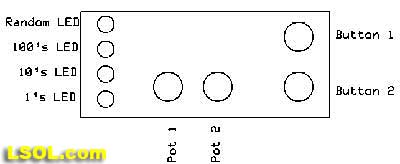
With the controls, display and hardware issues settled the unit looked like this. The four LEDs are to the left, the two adjustment potentiometers are at the bottom and the two setting buttons are on the right.
Software, the Magic that Makes it Work!
A microprocessor based device can have the greatest hardware in the world but it won't do anything without a computer program, or software, to tell it what to do. Designing such software can be the most challenging part of a project like this but it can be great fun, too, as you make the lights and controls come alive to do your bidding!
Routines needed to be written to do various tasks that included:
- flashing the 3 number LEDs to represent a particular value
- reading the two pots to get input on time and speed
- reading the two buttons and performing specific tasks based on when they are pressed or held
- keeping track of the time that has passed since the train was last reversed
- keeping track of the number of reversals, or laps, that have been completed
- identifying a point on the track where the train would decelerate.
End User Instructions One of the other important considerations, which is intimately tied to the hardware and software, is the way that the end-user will interact with the device. This can be the toughest part of the design as one needs to anticipate how users will interpret instructions and, more importantly, how they will misinterpret them!
Connections
There are only two sets of connections on the auto reverse controller. One pair of wires goes to the track, between the two diode protected sections. The other connection is to DC power. This unit will operate most small G scale trains with just a 12-20 volt, 1-2 amp wall wart power supply. The only other consideration is to make sure that proper polarity is observed as connecting the positive and negative wires from the power supply backwards can damage the components.
Making it Work
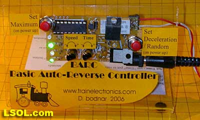
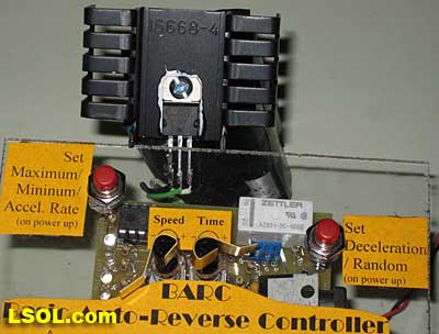
The finished unit is pictured below. You can see the 4 LEDs on the left (2 are illuminated here), the two switches are the red devices labeled Set Maximum and Set Deceleration/Random and the two potentiometers are labeled Speed and Time. The circuit board and electronic components are also visible through the clear plastic mounting stand. The microprocessor is the black rectangle in the upper left corner. The white object in the upper right corner is the reversing relay. On top of it is the power transistor that controls the train's speed. The unit also has a name, BARC - the Basic Auto-Reverse Controller.
To give you an idea of how it works here are the Quick Start notes that are printed on the base of the unit followed by some additional comments.
| Quick Start Set Maximum / Minimum Speed - on startup hold "Set Maximum" Button; Release once 2 lights blink "up" - use ;Speed; pot to adjust top speed - push "Set Deceleration" button to toggle direction "Press "Set Maximum" again
2 lights blink "down" - repeat procedure for minimum speed. " press "Set Maximum" again when done or hold for 3 seconds to set acceleration rate (see manual) Set Time - use "Time" pot to vary delay time from 3 to 512 seconds Set Deceleration Point - as the trolley runs briefly press the "Set Deceleration" button until the lights flash Activate Random Time - Hold "Set Deceleration" button at power up - Random LED will light - repeat to turn off Full Reset - Hold both buttons for 3 seconds on power up - lights will flash - release when lights stop flashing |
Set Maximum Speed - This button does a number of things. If you hold this button when power is first applied you can set the unit's top speed. As the notes above suggest when you hold the button on power up the 10's and 100's LEDs will blink "upward." While this is happening put an engine on the track and turn the Speed pot until the desired top speed is reached. If you are on a short length of track and the engine gets to the end just push the "Set Deceleration" button and the engine will change direction maintaining the same speed. After setting Maximum Speed press the button again and the 10's and 1's LEDs will blink "downward." Repeat the speed setting to set the minimum speed. Make sure you set it high enough to keep the engine from stalling, especially if part of the point-to-point is on an incline. Press the button again when done (the unit will remember your settings) or hold the button for several seconds until the flashing LEDs stop flashing. This will put you into the acceleration setting mode. Rotate the Speed pot. The full counter clockwise position gives a very fast acceleration / deceleration while the full clockwise position gives a very slow, gradual rate of change. The trolley will continuously accelerate & decelerate to show your selected setting, pausing for1 second at the maximum speed and again for 1 second at the minimum speed. Remember that briefly pressing the "Set Deceleration" button will reverse the trolley should you run out of track. Briefly press the "Set Max/ Min" speed button when done.
Set Time - If none of the buttons are held when the unit is first turned on the 3 number LEDs flash together showing the version number of the software. (Version 5.2, for example, would flash 5 times, pause briefly, then flash 2 times). During this flashing you have an opportunity to change the time setting by rotating the time pot. The time potentiometer, the one to the right, makes time adjustments. Turning the potentiometer counterclockwise decreases the time and turning it clockwise increases the time. The time range is from a few seconds to 512 seconds, a bit over 8 1/2 minutes. You will note that there is a slight detent, or bump in the potentiometer movement, that you can feel when you pass the center point. When you change the time the LEDs will flash out the new setting 3 times before it memorizes it. You can continue to fine tune the time until you allow the new time to flash 3 times.
Set Deceleration Point - As the trolley approaches the end of its run you can set a deceleration point where the BARC will slow the trolley to its minimum speed as it enters the diode protected end of the track and stops. Hint: let the trolley run a few laps before setting the deceleration point. Briefly press the "Set Deceleration" button when you want the deceleration to begin. The LEDs begin to flash rapidly. Note that once the trolley starts running at its minimum speed you can use the speed potentiometer to adjust the low speed setting. This will be necessary if the speed is set so low that the trolley stops rather than slows to a crawl. Once set the BARC will remember the deceleration point until you choose another, earlier deceleration point. If you want to do a later deceleration point do a complete reset first.
Activate Random Time - If you hold the "Set Deceleration" button when the power is first applied the Random LED will light indicating that a random time will be used. Repeat this procedure to disable the random function. The random time is computed by taking 1/2 of the time you have chosen and adding a random time between 0 and 1/2 of your time to it. For example, if your chosen non-random time were 120 seconds the random time would be between 60 and 120 seconds. If you chose 222 seconds the random time would be between 111 and 222. Using this formula insures that your trolley will have enough time to traverse the track before it reverses since the time is never less than 1/2 of what you have selected.
Full Reset - The BARC can be completely reset to its factory configuration by following this procedure. Turn the BARC off. Depress BOTH the "Set Deceleration" and "Set Maximum" buttons. Turn on the power to the BARC. All four LEDs will begin to flash. Hold the buttons until the LEDs stop flashing. This takes about 3 seconds. Release the buttons and all is reset. Releasing the buttons before the LEDs stop flashing will abort the reset
The video below shows the basic operation of the BARC, including:
- Holding both buttons on power-up to show full reset
- Holding the Set Min / Max button on power-up and using the Speed pot to set maximum and minimum speeds
- Setting the total run time with the Time pot
- Setting the deceleration point with the Set Deceleration button
*Note the change in the direction of rotation of the engine's wheels at the end of each run segment as the relay reverses polarity.
Additional information on the operation of the unit is available on www.TrainElectroincs.com .
ONBOARD OPERATION
There was one other objective that was in the list that we have not touched on, "the capacity to operate onboard a battery operated train." I didn't really design the circuit from the ground up to operate independently on a train but have tried it and it works surprisingly well. Several things need to be done to install the unit on a battery operated train. Batteries and the BARC can be mounted in a trailing car. The engine needs to be modified so that the track power output wires on the BARC can go directly to the engine's motor. The specifics of how to do this are beyond the scope of this article but most engines come with a wiring diagram that should help. The old LGB engine that I used for testing had power connections on the back of the cab that made setup extremely easy. Just make sure that you don't have another power supply connected to the track as the battery supplied power may go back to the and cause problems. I always physically disconnect track power when working with battery powered trains!
The biggest challenge is setting the maximum and minimum speed as the unit assumes that the train is moving but that the controller is NOT! You can start the controller and follow along the track adjusting the speed and pushing buttons or you can just lift the engine's wheels from the track (or put the engine on rollers) as you make adjustments. I have used both methods successfully but the first one is a bit more challenging!
You may want to set the minimum speed low enough to almost bring the engine to a complete stop. Since there are no cut sections of track with diodes to stop the engine you will have to depend on bumpers at each end of the track to guarantee a full stop. I have also used the unit on my mainline loop where it adds some variety to the train's activity. I set the timer for 512 seconds and RANDOM and it accelerates from a stop, runs for several minutes before decelerating, stopping, pausing, reversing, accelerating and doing it all over again!
A LAST MINUTE UPGRADE During testing I found that the power transistor, a TIP101 Darlington, could get quite hot when the power supply was at 24 volts and the engine was drawing over 1/2 amp. On a number of occasions the metal tab on the TIP101 was too hot to touch. I measured the temperature as being in excess of 150 degrees F.
Although this was within the design specs of the transistor I wanted to try and make this device run cooler. The solution that I settled upon was to replace the NPN Darlington transistor with an n-channel mosfet, an IRL520N. Mosfets have a much lower internal resistance when turned on than the Darlingtons. This means that they run much cooler as less energy is converted to heat. With the substitution of the mosfet the device's temperature under the same conditions was less than 115 degrees Fahrenheit. Quite an improvement!
I also built a test unit with the mosfet mounted externally so that I could include a heat sink. This was accomplished by removing the device from its socket and soldering the mosfet to three short lengths of wire that were soldered to the circuit board behind the socket. The additional length of wire allowed me to put the mosfet and heat sink under the circuit board. Adding the heat sink gave the unit the capacity to operate engines that were drawing well over 2 amps. Since the IRL520N is rated for 10 amps and is able to dissipate nearly 50 watts that is well within the device's specifications.
I hope you found this description of how a complete unit can go from initial concept to completion. If you would like to give it a try on your railway complete units are available directly from the author. buildingisit www.TrainElectronics.com for details or if you would line information on how this unit can be customized to fit your needs.
Top of Page