Power, Sound, R/C
:
Lights / LED
LEDs 102 - Use On Board Trains
Sep 5, 2007


By David Bodnar
LSOL.com Electronics Editor |
Author
Bio
LEDs 101 - The Basics, served to review the characteristics and use of LED lighting in a garden railway environment. It also generated a host of questions and comments that indicated that there was an interest in using LEDs in a variety of ways that were not covered in that article.
|
 Introduction The first article in this series, LEDs 101 - The Basics, served to review the characteristics and use of LED lighting in a garden railway environment. It also generated a host of questions and comments that indicated that there was an interest in using LEDs in a variety of ways that were not covered in that article. In this installment we will look at a number of things that you can do with LEDs on your layout. These will include: - Getting power to LEDs that are installed on board trains
- Reducing flicker in LEDs that are powered through track pickups
- Installing directional LEDs that are wired so that one LED lights when an engine is going forward and another lights when it is going backward.
- Using LEDs to illuminate the interior of cars
- Choosing batteries to power on board LEDs
- Using LEDs with track power on DC and DCC layouts
Getting Power to LEDs on Trains There are a number of methods of getting power to LEDs that are used to illuminate trains. Supplying power to LEDs that are inside of engines is the easiest. Since most engines are already electrically powered all we have to do is to tap into the power that goes to the motor and condition it a bit and we are in business. Many engines even have bridge rectifiers or diodes to maintain polarity and voltage regulators that provide a consistent voltage. If your goal is to add LEDs to an engine you can consult the wiring diagram for the unit or poke around the engine's circuit board with a volt meter to determine a good location to gather power. Ideally you want to find a place where the voltage is consistently no more than 5 volts and where the polarity is always the same. If you don't have any luck locating such a power point yourself, the LSOL forums are a great place to ask for help. If you can locate the engine's circuit board just post a few close-up photos and a description of the board in the forums. In no time at all forum users, including yours truly, should be able to suggest wiring options. Here is a good example. The photo below is from the power board on a Bachmann 45 Ton Switcher. The three devices on the board are marked 7812. These are 12 volt voltage regulators. They are used to provide no more than 12 volts to the smoke units on this engine. You can tap into their power output and use it to power your LEDs. Any of the three regulators can be used. The center pin is negative and the pin to the right (the one not marked "IN") is positive. The only problem with using this to power your LEDs is that they will not light up till the track power is a volt or two above 12 volts. If you can find a voltage regulator marked 7805 it is a better choice as it provides 5 volts and will illuminate the LEDs when only 6 or 7 volts is on the track. If you are comfortable adding your own 7805 voltage regulator just use the center pin (ground) again and the pin marked IN as the input for the 7805. 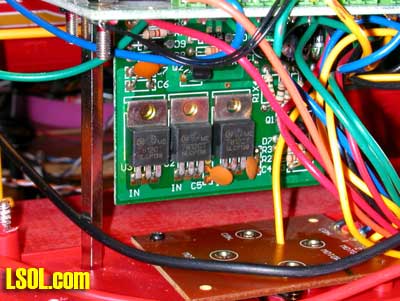
Providing power to illuminate rolling stock is another matter. If you are powering your trains through the track metal wheels with electrical pickups are the obvious solution. You can also run wires back to each car from the locomotive where you can tap into the electrical power that is found there. The easiest method is to install a battery on each car. The drawback to battery power is the need to periodically replace or recharge the batteries. You also need to install a switch to turn the lights off and on so that the batteries are not depleted prematurely. Polarity Matters When powering LEDs from batteries polarity is consistent and not an issue. Track power, however, presents a problem since either rail can be positive or negative depending on the direction of the train's travel. Fortunately there is a simple electronic solution to this problem, the bridge rectifier. (Note that this topic has already been covered in some detail in the LSOL article 5 Volt Power for Railway Electronics ) 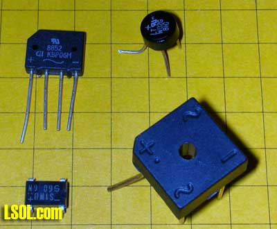
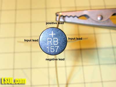
Bridge rectifiers have two input pins (frequently marked with the symbol for alternating current "~") and two output pins that always provide a positive and a negative terminal no matter what the polarity may be on the input terminals. The input pins go to the track pickups and the output pins go to the LED(s). In the photo above you can clearly see the markings on three of the four different bridge rectifiers. The exception is the round device in the upper right corner. It is marked with only a "+" - in this case the negative terminal is opposite the "+" and the input terminals are the remaining two leads.
You will also note that the positive lead on bridge rectifiers is generally longer than the other three. The size difference between the bridge rectifiers in the sample is due to their current handling capacity. The largest is rated at 3 amps and the smallest at 1 amp. LEDs draw so little power that any size bridge rectifier is likely to suffice. If you were to look inside of a bridge rectifier you would find four diodes arranged like this: 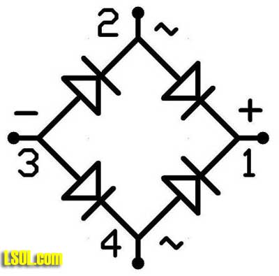 The voltage of unknown or varying polarity goes into pins 2 and 4 and the output is on pins 1 and 3. The only significant drawback to using a bridge rectifier in a circuit is that the output voltage is about a volt lower than the input voltage. Keep in mind that you can make a bridge rectifier from four diodes by wiring them as in the illustration above. I have done this on a number of occasions when I didn't have a bridge rectifier on hand or when I needed a particularly small unit.
Wiring LEDs for track power is straight forward. First you need to get power from the track. LGB and other manufacturers make pickups that can be added to trucks on rolling stock. Here is a photo of LGB's part # 63193 that can be used with just about any truck that has metal wheels. LGB's ball bearing wheel sets (# 67403) contain built-in power pickups but I find the 63193 to be a less expensive alternative if you already have metal wheels for the car you want to illuminate. 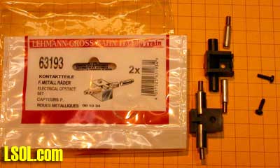 In this photo the LGB pickups have been installed on a Bachmann car with metal wheels. Note that you must solder wires to the body of each pickup before installation. 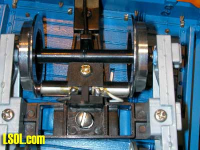
The two wires from the track pickups are routed through a hole in the car's floor and connected to the input terminals on the bridge rectifier. The output terminals go to the LED circuit. 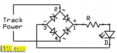
This photo shows the circuit above along with the truck pickups that power it. The alligator clips supply power to test the circuit. 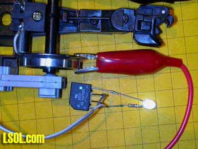
Additional LEDs can be added to the circuit. To properly illuminate the interior of a large passenger car you might use 5, 10 or even more LEDs. Those of you who have experimented with LED lighting may notice that there is a problem with this circuit. The LEDs are likely to flicker as the train rolls along the track. This is due to minor interruptions in the connection between the wheels and the track. Incandescent bulbs will also flicker when powered from the track but not as noticeably as LEDs. The reason for this is that LEDs can turn on or off in milliseconds in response to power variations. Incandescent bulbs, on the other hand, tend to glow for an instant when power is removed lessening the flicker.
This problem with LEDs can be corrected to some extent by adding power pickups to each wheel but there is a simpler, more economical solution. An electrolytic capacitor can be wired in parallel with the bridge rectifier's output. The capacitor will serve as a temporary power reservoir that will keep the LEDs lighted when power interruptions occur. Make sure you put the capacitor on the output side of the bridge rectifier as electrolytic capacitors have a positive and a negative terminal and have been known to explode if wired backwards! 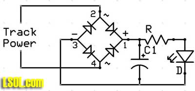
In this photo a 3300 uF / 50 volt capacitor is wired directly across the output terminals of the bridge rectifier. The lighter colored band on the capacitor shows the negative terminal. This is a fairly large capacitor but it almost guarantees that you will never see an LED flicker. The single bright white LED shown stayed illuminated for a full 5 seconds after the power was removed! Adding additional LEDs will shorten this time but it is still likely to keep things lit up while traversing track imperfections. 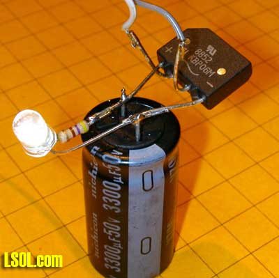
Additional LEDs can be added by wiring them in parallel as shown here. 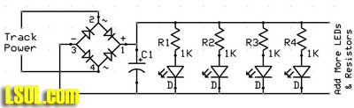
The photo below shows the circuit above. The track power comes through the wires on the left. The output of the bridge rectifier is connected to the capacitor and then to a positive bus (lower wire) and a negative bus (upper wire). The four LEDs and their four current limiting resistors are connected between the positive and negative leads. 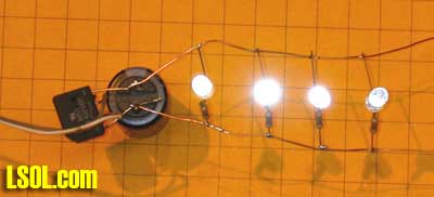
Selecting Capacitors Capacitors have two characteristics that define them, voltage and capacitance. The voltage on G-Scale track can be as high as 23 or 24 volts. The rule of thumb is to use a capacitor that has double the voltage rating that it is likely to see. In our case a 50 volt rating would be good. Many capacitors are rated for 35 volts and, even though this is lower than what many would recommend, I have used 35 volt rated capacitors for years without any problems. The capacitance is the amount of power that the capacitor can store. The higher the number the longer the LEDs will stay lit where there is an interruption in power. Any value above 300 uF (mfd) is adequate. If you want your LEDs to stay on for several seconds or more, and you have room, you can go as high as 50,000 uF (mfd ). 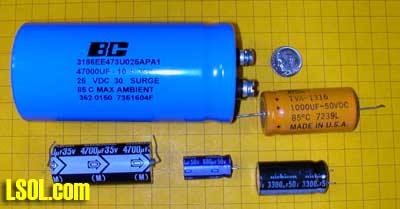
The capacitors in the photo above range from 680 uF @ 50 volts (bottom center) to 47,000 uF @ 25 volts in the upper left. Note that the large blue capacitor is rated at only 25 volts and may not be adequate if you tend to run your trains at full voltage.
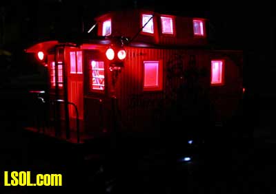
Mounting LEDs Inside of Cars There are many different ways of mounting LEDs to the inside of cars. Most involve mounting the LEDs on the ceiling of cars with the LEDs pointing down. The simplest involves just gluing the LEDs to the ceiling and routing the wires to the circuitry that is mounted on the floor of the car. The three bright, white LEDs in the photo below are the ones illuminating the caboose interior that is shown in the first photograph in this article. 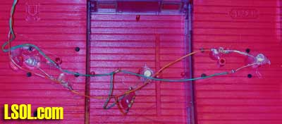
Depending on the size of the capacitor that is used the rest of the circuitry can be easily hidden, or painted and decorated to look like a stove. 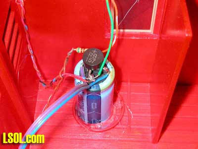 The green and orange wires that come off of the capacitor in the photo above go to the roof LEDs. The two wires that are twisted together on the left go to small 3mm LEDs that were inserted into the bottom of the side lanterns on the caboose as seen below. They are quite bright as you can see in the opening photo of the caboose at night. 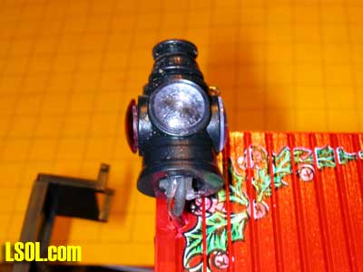
If you would rather not glue LEDs to the ceiling a neater installation can be done utilizing pop sickle sticks or similar strips of wood. The photos below show the top and bottom of a pop sickle stick that supports three LEDs and their current limiting resistors. Note that the orange wire connects to the positive terminal of the circuit and the white wire to the negative. 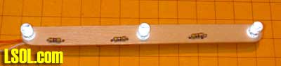 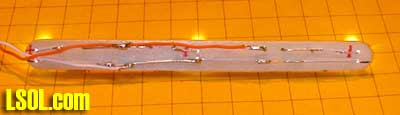
Directional LEDs Since LEDs only illuminate when the anode is connected to a positive terminal and the cathode to a negative terminal it is a simple matter to wire two LEDs back-to-back so that one lights when the train is going forward and the other lights when it is going backward. Most G scale trains are designed so that they go forward when the power supply connects the positive terminal to the fireman's (left) side and the negative terminal to the engineer's (right) rail. You will note that this is the opposite of what is done with HO locomotives, generally referred to as NMRA Standard. In the schematic below LED1 lights when the battery (or track power) is connected as shown. Note that no harm comes to LED2 because of the reverse wiring because the 470 ohm resistor in series with it limits current flow to a safe level. When the battery (or track power) is reversed LED2 lights and LED1 is off. 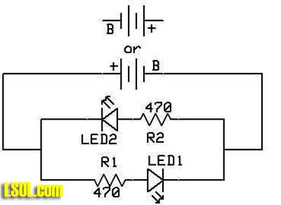
If LED1 is the locomotive's headlight it will light only when the train goes forward. If LED2 is a rear facing spotlight, as we see on some tenders, it will only light when the train is going backwards. Is it necessary to have both LEDs in the circuit? The answer is no. To have just a headlight work when the engine is going forward remove LED2 and resistor R2 from the circuit. If you are using a power supply that utilizes PWM (Pulse Width Modulation) to vary the voltage on the track you may see that LEDs that are supposed to go on only when the train is going forward light to some extent even when the train goes the other way. This is due to the back EMF that is generated by the train's electric motor. A discussion of back EMF is beyond the scope of this article. A Google search and some reading is recommended for those wanting more details.
DC and DCC and LEDs There has been some discussion about differences in using LEDs on DC (normal PWM or analog track power) and DCC (Digital Command Control) layouts. The good news is that the LEDs don't much care and that a circuit that works on a DC layout is likely to be happy and to perform well on a DCC layout with two differences. The main difference between the two methods of delivering power to trains is that DCC applies a consistent voltage to the track. Whether the train is moving or not the track still has 20 or more volts on it. This constant DCC voltage will keep all of the lights on in the cars whether the train is moving or still. This is a good thing. The other difference is that the directional LEDs that are shown above will not work as DCC changes polarity many times each second providing the same AC-like voltage if the train is going forwards or backwards. The good news is that most DCC controllers have LED connection pins that can be wired to forward and/or backward facing LEDs that will properly react when the engine goes forward or backward. You also have an option with DCC to turn LEDs wired to the controller on or off via a DCC command. Batteries for LEDs If you choose to illuminate your cars with battery powered LEDs there are a number of battery configurations you can use. The smallest and simplest is a non-rechargeable alkaline 9 volt battery. It will power most LEDs but only for a relatively short time. Most alkaline 9 volt batteries will only provide power to 5 white LEDs (each drawing around 20 ma) for 4 or 5 hours. This time can be extended by increasing the value of the current limiting resistors on the LEDs to 1000 or more ohms. The disadvantage is that the LEDs will be somewhat dimmer. Four non-rechargeable AA alkaline cells wired in series can light the same 4 LEDs for four or five times as long. If space is not an issue they are a better choice.
Rechargeable nickel metal hydride (NiMH) AA cells usually have their power rating printed on the label. If you wire four 2000 milliamp hour AA cells in series they should power the 5 white LEDs for 20 hours. I would suggest avoiding nickel cadmium cells as they take up the same space but provide much less power. If you choose to use rechargeable cells you can mount them on the bottom of your car for easy replacement or recharging. If you place them inside of the car you will need to provide a power jack through which they can be charged. If you choose to charge batteries that are inside of cars make sure you use an intelligent charger or one with a timer that will not overcharge and cook the cells. I prefer to charge batteries outside of cars and engines so that I can monitor the temperature of the cells as they charge. 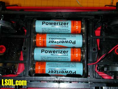
If your car does not provide enough space for a battery holder and 4 AA cells as in the photo above, NiMH cells are also available with solder tabs so that you can make a smaller battery pack by soldering cells together. Turning LEDs On & Off in Battery Operated Cars A simple SPST (single pole single throw) toggle switch is the easiest and most effective way to turn battery operated LED lighting on and off. The main problem associated with the use of such a switch is finding a convenient mounting location that doesn't take away from the looks of the car. Placing the switch under the car is the most logical choice even if it can make locating and throwing the switch in the dark a challenge. Magnetic reed switches provide another option for activating battery powered LEDs. Most reed switches are normally open and only conduct electricity, turning a circuit on, when a magnet is in close proximity to the switch. A reed switch, glued to the inside of a car's roof, will turn lights on when a magnet is laid on top of the roof area directly above it. If you are willing to leave a small magnet laying on top of a car you can use this method to turn your LEDs on and off. As an added bonus the reed switch and LEDs draw no power when the magnet is removed so that the batteries will last indefinitely when the LEDs are off.
I have read about reed switches that latch on or off depending on which of the magnet's poles is placed near the switch. This sounds like a great way to activate our LEDs but these latching reed switches seem to be a rare commodity as I have not been able to find a reliable source for them. Until such devices become commonly available I have put together an electronic circuit that does the same thing utilizing a single integrated circuit and a commonly available reed switch. Rather than delve into the on/off circuit at this time it, along with some other "on/off" ideas, will be the focus of a future article. Stay tuned! Top of Page
|


