Track & Bridges
Casting Concrete Abutments
Part II
Feb 28, 2007


By Glenn Habrial |
Author
Bio
As I ended Part I, the mold for the abutments had been filled with the Vinyl patching concrete and the mold was shaken with the saber saw minus the blade to remove the air bubbles. We had left it to cure for a day. This was where things got interesting.
|
As I ended Part I of this article, the mold for my abutments had been filled with the Vinyl patching concrete and the mold was shaken with the saber saw minus the blade to remove the air bubbles. We had left it to cure for a day. Casting Concrete Abutments - Part I This was where things got interesting. Did the mold get shaken enough to knock all of the air bubbles loose? Was the mix sloppy enough to fill all the crevices? Was the mix dry enough not to run in between all the plywood laminations and cause separation of the cheap plywood? Did the rebar shift and become exposed as in the first pour? Would the abutment come out of the mold without breaking? Would the mold remain intact after the abutment was taken out of the mold? 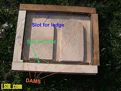
Let's find out!!! When the concrete was cured enough to remove from the mold, the mold was flipped over. The screws for the dams (the ones around the outside of the back plate.) were pried off the dams. Two 4" X 4" blocks were placed just far enough apart on the floor to support the back plate with the concrete abutment between them. Putting some weight on the mold back plate to flex it a bit I attempted to remove the abutment. (The abutment held fast.) So I rotated the back plate and set the sides next to the 4" X 4" blocks. (The ledge and foot were next to the 4" X 4" blocks and 2" X 4" blocks would have worked.) Again the abutment held fast to the mold. I then found a bunch of large straight slot screwdrivers. This time when I flexed the back plate, I slipped the blades of two of the screwdrivers between the abutment foot and the mold back plate. I did the same between the ledge and the back plate. This seemed to free up the abutment from the mold a bit. It also broke off a small section of the corner of the ledge. I was not too concerned, as this would give it a realistic look when the abutment was installed. After some more careful prying with the screwdrivers, the mold gave up the concrete abutment. 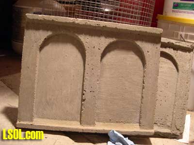 Did I shake the mold enough to remove all the voids and air bubbles? The answer was a big Maybe. And was the mix sloppy enough as well. Maybe again.
There were some voids on the center column and these can be seen in the picture. On the failed first pour, I mixed and poured the concrete in layers. It seems that I didn't mix enough concrete the first time. My first batch was quite dry and didn't have much slump. (Slump is when there is enough water in the mix for it to slide into a mold and seek its own level. A lot of slump means the concrete will not pile up.) As water was added to the mix, a ratio was reached where the mixture becomes the more like mud than wet sand. A few drops of water made the difference between too dry and just right. When there was not enough water, it was easy to remedy, except after your first pour of concrete was already in the mold. The first batch I put into the mold was of the wet sand consistency. Since I was worried that there might have been too much water, I hesitated to add more. That caused my concrete to be too dry. Concrete expert's say: "Use a trowel to smooth the top surface of the concrete, then chop it to make a groove about two inches deep. If the cut stays smooth and maintains its shape, the ratio of water and concrete is at the correct consistency. If the walls of the groove are not smooth then more water is needed. If the walls fill in the groove, there is too much water and more dry ingredients need to be added to the mix." Other experts recommend the wet concrete be the consistency of pancake batter and I thought I would follow their model. For my purposes, I wanted the consistency of the concrete to be slightly on the watery side. However, since my concrete consistency was too dry I was concerned that it might affect the strength of the concrete in the future. (But then, how much weight will be applied to the abutment?) I took the abutment out of the mold with little damage to the mold. So the mix was good enough to keep the mold from suffering any further damage. I also noticed that the rebar could not be seen from either the front or back.
After removing it from the mold, I cleaned off the abutment and painted the exposed surfaces to reduce the effects of acid rain. (The New Jersey area sees a lot of damage to concrete structures from this phenomenon.) Since the abutment was relatively thin, even light deterioration from acid rain could be severe. At this time I decided to weather the abutment. Since the bridge was resting on it is simulated steel spacers, I tried to simulate rust stains from the spacers. I looked at another prototype concrete abutment to get the idea for how to make the rust stains. I saw two types of staining on the real abutment. One kind of stain was a general area staining and the other was a very concentrated streak of stain. These stains appeared on the same prototype abutment. So I created both types on my abutment. My abutment is stained with a light overall patina of rust with heavy streaks that do not reach the ground. 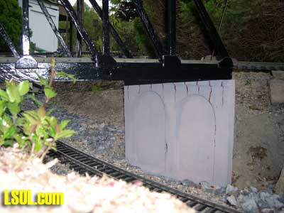 
Next I prepared the garden for the abutment. This involved digging down along side the track to place foundations for the abutments to rest on. Since I was installing this abutment under track that has been in place for years, I measured the location carefully. I was also concerned that when the train ran under the bridge, the side of the train might drag on the abutment. I found my longest car and checked the clearance. Another thing I realized after I built the bridge was that most prototype bridges on the line that I was loosely modeling were as short as was absolutely required to span the gap. This meant that the abutments would sit very close to the tracks. Since the price of bridges was measured in dollars per foot and the cost rose exponentially with the length of the span, dirt fills were a lot more cost effective than a longer span. I had already built another bridge for my railroad that was longer than was strictly needed and I didn't want to do that again. When most of the prototype bridges being modeled were built, they spanned several tracks. Today just one track of those tracks remains. That is why when we look at bridges today there seems to be a lot of unused space between the track and the abutment. This is probably true for many areas of the country. This gave me an excuse to add a siding track going under my bridge. 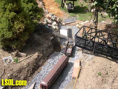
The walls and bottom of the hole for the foundation were to be directly against the concrete, and needed to be smooth. After the hole was dug, it was to be filled with concrete to form the foundation that the abutment would rest on. It was imperative that the foundation, or more commonly called the footer, was absolutely flat. The bottom of the footer was below the frost line as well. (The frost line is the depth in the ground that gets cold enough to freeze in the winter.) Some winters are colder than others, and the frost line gets deeper. Lately the frost line hasn't been that deep in northwest New Jersey. The reason the bottom of the footer needed to be below the frost line was that when water freezes it expands. The soil holds water and when that water freezes it pushes up whatever is above it. This is called frost heaving. The footer must be absolutely level. You would think that concrete in the liquid state would seek its own level. That is not the case as concrete isn't a true liquid but a mixture where the top surface can be sloped. To make the top of the footer level two small stakes of the same length are put in the hole when the concrete is poured and once the concrete settles in the hole the tops of these stakes should be level with each other. If you put in a bigger footer more stakes will be needed. The top of the stakes must be at the exact height that you want the bottom of the abutment. This is kind of like a math problem. Measuring from the bottom of the track, the thickness of the bridge (1 inch) plus the height of the abutment (10.5 inches) equals the distance to the top of the stakes. (11.5 inches) Wait a minute; this is a math problem (I hate math!). Of course, I had previously determined how high the track and bridge had to be over the track in the cut (10" inches) and made the abutment for that height. In the photo, the tape measure is clamped to the bridge at the 11.5-inch mark. 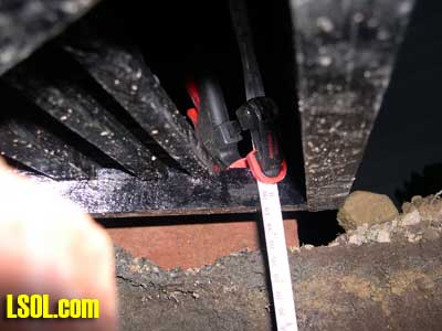
In this next photo, the top of the stake needed to be set about an eighth of an inch deeper. I had planned for the bottom of the abutment to be below grade level in the cut. That meant I did not have to build a frame for the footer. That is how the real railroads usually put them in. 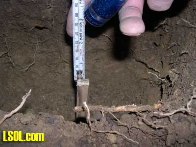 Once the stakes were set to the correct height and level with each other the hole was ready for the concrete 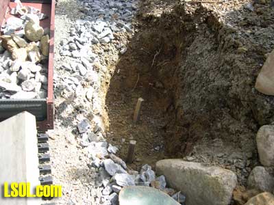
For the footer I used the standard Topping (sand) mix concrete. This concrete had small aggregate (the stones that the cement in the mix sticks to) of about 1/4 inch and smaller in size. I mixed the concrete to get the right slump (not too much water) and poured the mix into the hole. Since I could not pre-measure how much concrete was to go into the hole I just guessed. It was an educated guess as I had a rough idea of the cubic inches of the hole (here we go with the math again.) The hole was about 12 inches long and 5 inches wide and the height of the stakes were about 6 inches. That equals roughly 360 cubic inches. (The sides of the hole are rough and my measurements were rough too.) The bucket that I mixed the concrete in had about a 10-inch diameter. That equated to an area of 78.5 square inches. (Remember area of a circle is Pi times Radius squared) Then I divided that into the 360 cubic inches and filled the bucket with about 4.6 inches of dry concrete, for the same volume. Ouch, that hurt the grey matter! I mixed up the concrete and poured it into the hole. As it turned out I was just shy of enough concrete. (So much for the math) After all, when concrete is mixed right, it sticks to the inside of the bucket, the trowel and everything else besides the hole. (Next time I will factor in a stickage overage percentage.) But fear not, this was just concrete in a hole, I simply added more aggregate in the form of a few driveway stones to displace enough concrete to bring it up to the correct level. Now, after I had the correct level and the mix was toweled level with the top of the stakes, I checked it with a piece of wood that had a straight edge. (Don't use the expensive level for this step.) I removed the stakes out from the concrete. If left in, these wooden stakes would have absorbed moisture and freeze in the winter. What happens when water freezes? It expands, cracks the footer and lifts up the abutment. I didn't need that.
Now that the footer was poured and cured a few days I took more measurements. I rechecked the clearance to the track in the cut, and the lateral location with reference to the track and bridge. In the pictures you can see faint chalk lines that mark where the abutment would sit on the footer. 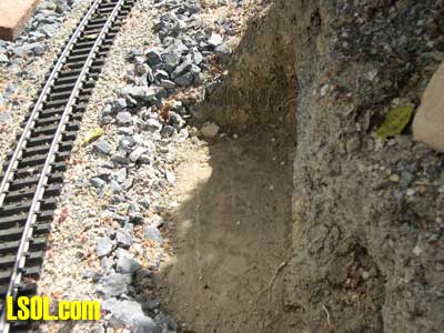 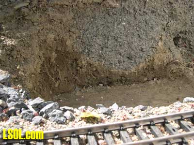
Next the abutment was glued onto the footer. There was a recent article in Garden Railways magazine about gluing bridge ends with Polyurethane glue, so I decided to try it. I used a paintbrush to clean off the top of the footer. In the process I brushed away most of the chalk marks. (Enough remained) I then applied the glue. 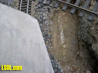 I wet the base of the abutment and that water activated the glue. 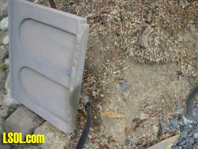
I positioned the abutment on the footer inside the remaining chalk mark. I put the bridge on top of the abutment with a few bricks to weight things down. The Polyurethane glue had hardened and you could see foaming around the seam and blossoms dropped from the nearby holly bush. These blossoms were brushed out of the way for the next step. 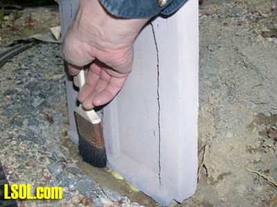 I next mixed up some sand mix concrete and filled the hole around the foundation to help hold the abutment in place. This was the same concrete that was used for the footer. I did this for two reasons: to give the joint more strength; and to make rainwater drain away from the joint to help it keep dry. This is very important in frost prone areas. 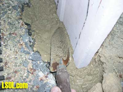
I needed a slope away from the base of the abutment to ensure the water would drain away. This area will eventually be covered in driveway stone so that water can move through the area and not pool around the base. While the concrete was setting up, I started on the other end of the bridge. The second abutment required a second hole to be dug and stakes set at the correct height. 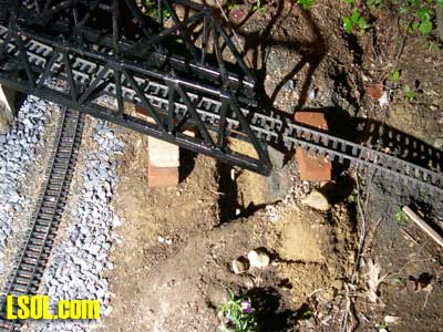 I followed the same procedure for the footer and installation of the abutment but I made sure the two abutments came out level by taking measurements and carefully leveling between the two. 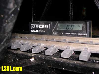
After the concrete had dried, I backfilled the abutment with driveway stone and began the fabrication of the wings. (Wings are the fill material along side of the abutment that keep the driveway stone in place.) 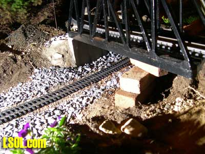 I used patch concrete as mortar around stones I found in the garden. I cleaned the stones with a brush before placing them so the concrete would get good adhesion. 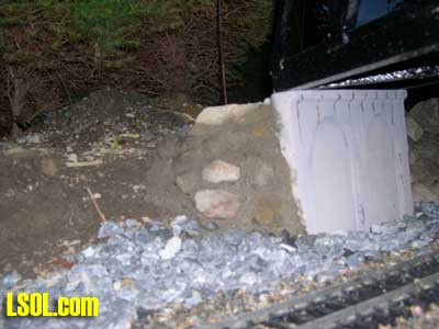
The other wing on the abutment was right next to the stone wall that was lining the edge of the cut. This wall was just stones with no mortar holding it in place. 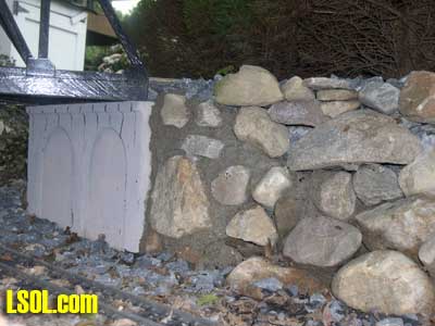 This wall was required because of the angle of the bridge. The bridge was built that way, because the tracks across the bridge do not cross the tracks below at a right angle. In the picture you can see I located the bridge a little close to the main line in the cut on the left side. Originally I was going to put the bridge a little to the left of where it is in the picture, but I decided to double track the cut under the bridge with a siding. I have not yet installed that siding. 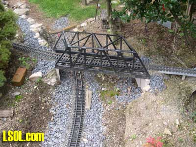
Since the other bridge abutment was set well back into the hill, there was no need for any kind of wing. After installing the abutment using the same methods as the first one, I backfilled the abutment with driveway stone and placed bigger rocks between the hill and the abutment. 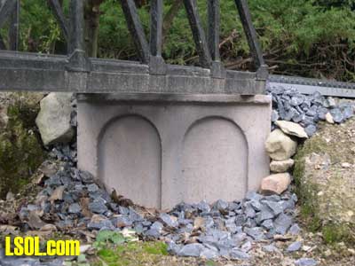 I left the bridge free-floating on top of the abutments, as I wanted to see how the freezing winter temperatures would affect the structure. If I decide to secure the bridge it will be only at one end so that things could shift around as necessary with the freezing and thawing. The things I have remaining to do are ballasting the approaches to the bridge and installing guardrails between the track rails. In the era I model, guardrails were a safety item. I am very pleased with my bridge and feel that my first attempt at casting abutments was pretty successful. If you have any questions about how the article, let me know. I hope this article will give some of you the courage to try something that you have not done before. One of the really fun things in Large Scale is that there are so many things that we can try. All it takes is the nerve to step up and start the project. The rewards are very gratifying. Top of Page
|


