Track & Bridges
Building a Set of Stub Points
Jun 8, 2005


By Geoff Horne |
Author
Bio
This type of points is by far the easiest for the home builder to construct.
|
This type of points is by far the easiest for the home builder to construct. The tools required are very basic and are:
- One good quality flat smooth file
- Small hobby sized hacksaw
- Or Dremel motor tool or similar with cut - off wheels
- Small drills 1mm and 1.5mm and 2mm
- Good quality soldering iron, minimum 150w
- Solder and paste soldering flux
- Fine wet and dry sandpaper
- Vice
- Track gauge Flat or roller gauge
- Track pins
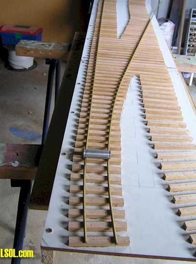
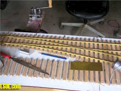
You will require some timber sleepers. In my case I usually cut them from pine if they are to be used on an inside layout or treated pine or hardwood if used outside. I cut all of mine on a Triton table saw to a size of 10mm x 12mm and cut them to length by using a drop saw with a very fine blade to a length of 100mm. Mark out where you intend to build these points and lay your sleepers. When I lay them for outside use I glue them firstly with water-proof white glue and then nail them with a small finishing style nail gun. These are such a handy piece of equipment and are now available for under $50. You will see that this section of track for Kato Creek is designed to have two sets of points to form a changeover. 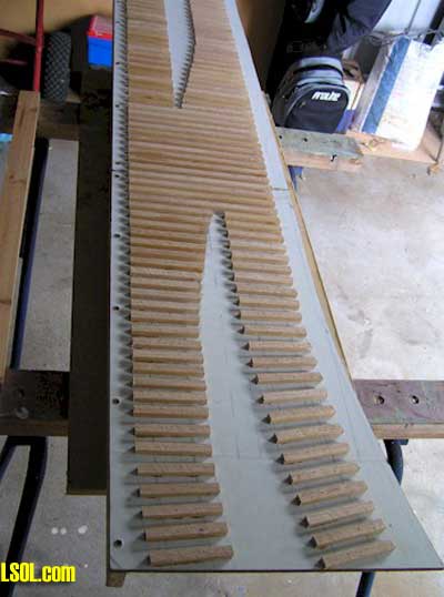
These will both fire at the same time with the use of two air cylinders. 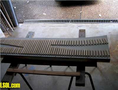
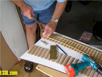
The baseboard is Weathertex in 9mm because of its superior resistance to anything that nature can throw at it. The sleepers in this case are home cut Tasmanian Oak hardwood. Firstly layout and fix in place the straight rail, but make sure that it has all of the necessary curves this section of track is curved at each end done before you pin it in place. To begin with only pin the rail at least ten (10) sleepers or ties away from the point where the straight track and the curved track are likely to spread out of gauge. The suppliers of the pins are such companies as Peco UK, Llagas Creek US and Micro Engineering US. I am sure that there are others around that may be able to help. I sometimes use 15mm x 18 gauge T nails that I use in my nail gun.
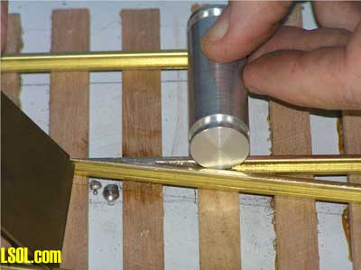
It just takes a bit of time to take them off the strip. The advantage to using these is that they are square and bite very nicely into predrilled holes. If you look around the tool stores you can also get them galvanised. They still rust but it only seems to be surface rust. I am using a Llagas Creek track roller to pre bend the rail before pinning it is place. 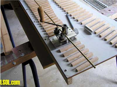
Now lay the curved rail and also pin this once about where the roller gauge indicates that they are getting further apart. Drill the flange of the rail and pin into place on the two sleepers.
This will then leave eight (8) sleepers that the rail is not fixed to. This is so that the rail can flex as you will see later. Now you need to pin the straight rail in this case at sleeper number 11 and then carefully using either a small hacksaw or a Dremel tool cut through both rails. 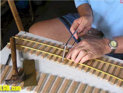
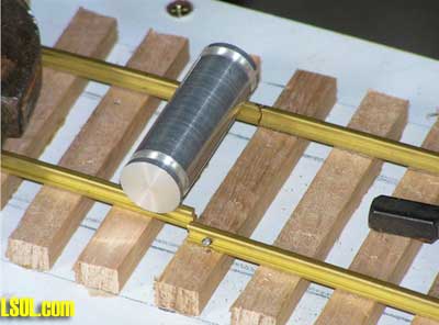
Now you have to pin the curved rail into position and this is done by moving the rail away from the straight one and rolling the gauge so that it clears the outside of it.
This is designed to emulate the width of the wheels of the locos and rolling stock and also a clearance so that nothing gets jammed up. This measurement can vary if you decide that you are going to model in fine-scale and you may then have to make your own gauges. I get all of my measurements from the Gauge One Model Railway Assn in the UK. Next, lay a piece of straight rail to match up with the incoming rail 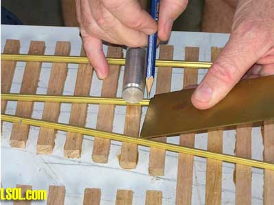
and then using a roller gauge and a flat gauge mark where it has to be bent to form the inside wing rail at the frog. This can be done in a vice for the heavier codes but can be quite easily done if using rail such as Peco by using a pair of pliers. 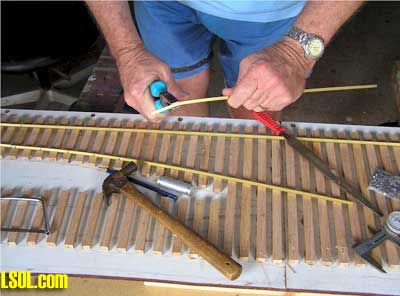
Now comes the good bit. MAKING THE FROG ! Don't freak out about it because after the first one you see there is nothing to be frightened about. Start off by using a piece of pre-bent rail and mark the angle that you either have to file or grind to match the points that you are making. With the two section of rail nicely filed and cleaned and free from any oil and grease they are ready to solder. Check that they are going to fit correctly by running the gauge along. 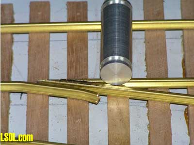
I suppose that I am spoiled in that I have a 300w soldering iron which makes very short work of this type of job.
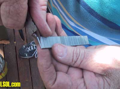
Next job is to apply a good flux onto the mating surfaces 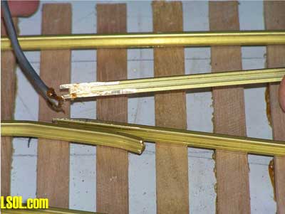
and then apply plenty of heat until you see the flux bubble and then run like water along the rail. Now apply some solder not fluxed available at plumbing supplies and let it run into the joint 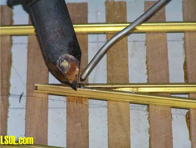
The solder should be very shiny when you finished. If it is a matte looking colour it is an indication that there is not enough heat and that the joint will be very brittle and break very easily. Don't worry if you get too much solder into it as it is easily removable with a file or two hacksaw blades side by side. File the excess solder off the top and the edges of the rail with a flat file. 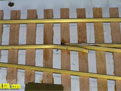
Now by using the two gauges set the point of the frog into position and drill and pin it into position and then position and pin the straight section of track. Repeat the exercise with the other short section of track and pin it into position measuring at all times with the gauges. Now, you should be feeling very pleased with yourself indeed. And it should now look like this. 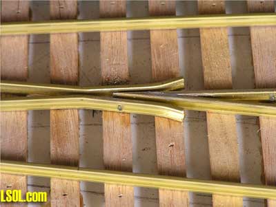
Measure and cut two short pieces of rail for the wing rails. Make sure that they are long enough to be functional, maybe 90mm long. Pin them into position and then try running a truck through. 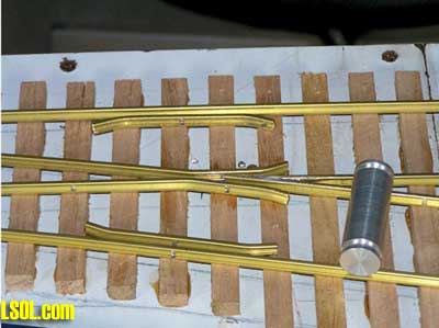
You now have to either solder of screw a tie-bar across the two lead in rails 
and a good idea is to pin a flat piece of .010 brass over the top of it 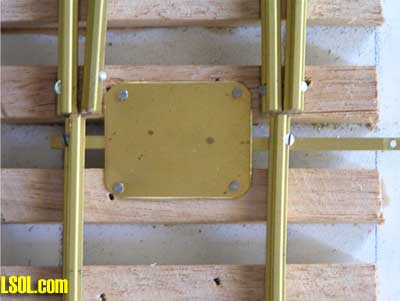
especially if using it outside and a small amount of Petroleum Jelly (Vaseline) on the bar first. The linkage is then attached to the bell-crank which in turn is connected top the air cylinder that will be used to operate them. 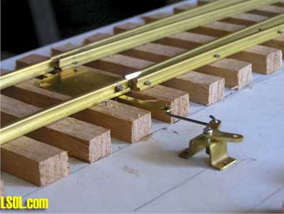
Now play with them, because you have just completed a very pleasurable project. If you have any tight spots while checking with the gauge it will only be a simple matter of a light tap with a hammer and nail punch. Then you will need to give the pin a light tap on the top again to make sure that it is set into position. I am sure that you will be pleasantly surprised as to how easily they go together and will soon be looking at somewhere else to put a set 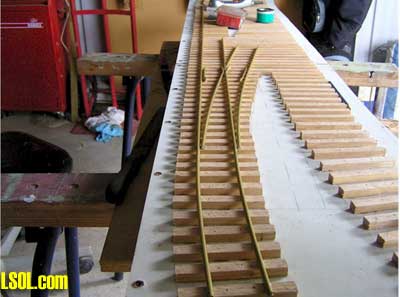
Top of Page
|


