Power, Sound, R/C
:
Remote Control
Automatic Switch Project - Part V Microcontroller Integration & Software
Jan 3, 2007


By David Bodnar
LSOL.com Electronics Editor |
Author
Bio
When I start a project like this I like to come up with a list of things that I would like the finished device to do. The list of objectives below are the things that the microcontroller must do to manage the proper operation of all of the individual modules.
|
All of the things that have been described and utilized so far need to be pulled together by an intelligent device, a PICAXE microcontroller, and a program that tells it what to do. When I start a project like this I like to come up with a list of things that I would like the finished device to do. The list of objectives below are the things that the microcontroller must do to manage the proper operation of all of the individual modules. Objectives The microcontroller that ties together the parts of this system must be able to do many things. Among them are: - Sense when a train gets to the end of a block (see part IV, sensors)
- Control turnout motors to direct trains into a particular siding (see part II, turnout control)
- Turn the power to a block on or off (see part I, controlling blocks)
- Display information on the system's status on an LCD readout (discussed in this section)
- Interact with the operator (discussed in this section)
- Recognize and react to error situations (discussed in this section)
Flowchart A flowchart is another tool that helps in software design. This list of tasks is a text based flowchart that shows what the software does: - Reset all block relays and set counters to zero
- Are all three trains waiting at their sensors?
- If no move each train forward a bit and go back to step 2
- if yes continue - Set turnouts to their starting positions
- Send train 1 out by activating block 1's relay
- Has train 1 cleared its sensor?
- If no go back to step 6
- if yes continue - Set switches so train 1 returns to its proper siding
- Has train 1 returned?
- If no go back to step 9
- if yes deactivate block 1 and continue - Send train 2 out by activating block 2's relay
- Has train 2 cleared its sensor?
- if no go back to step 12
- if yes continue - Set switches so train 2 returns to its siding
- has train 2 returned?
- if no go back to step 15
- if yes deactivate block 2 and continue - send train 3 out
- has train 3 cleared its sensor?
- if no go back to step 18
- if yes continue - Set switches so train 3 returns to its siding
- has train 3 returned?
- if no go back to step 21
- if yes deactivate block 3 and continue - Report laps
- go to step 5 and repeat
As you can see the logic is not too complex. In addition to what is listed above the software continuously does three other things: - Displays each train's status on the LCD display (which train is out, has it cleared its sensor, how many laps completed, etc)
- Checks the trains that are not running to make sure that they are still at their sensors. If it finds that a train is not where it is supposed to be all blocks are shut down and an error message is reported.
- Looks for activation of a radio controlled switch that tells the system to stop all trains once the currently running engine returns to its block sensor. This is an easy for the operator to shut things down at the end of the day.
The Circuit The schematic below should look familiar since we have used parts of it in the other articles. In this diagram all of the pieces are connected to the PICKAXE 28X. This device is similar to the other PICAXE chips that we have used except that it has 28 pins. I chose to use it because of the number of devices that need to be observed and controlled. The cryptic notes that you see on the schematic (such as bw / ow and sensor3=green) are there to help me remember what color wire I used to connect various things (bw=blue/white wire, ow=orange/white, etc) 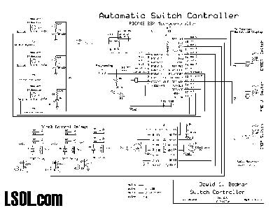
Click for larger image
The one thing that is not included in the schematic is the LCD display. To simplify the project and speed its time to completion I opted to use an external LCD display controller. This is a chip from www.phanderson.com that accepts serial input at 2400 baud and displays the information that it receives on a 4 line X 20 character backlit LCD display. A complete description of the chip and its use is available at: http://phanderson.com/lcd106/lcd115.html . This unit and others from Peter Anderson are highly recommended.
Software The software listing is available for viewing or download by clicking this link. View/Dowload Software It is fairly well commented and, for the most part, follows the logic that is described above. The items following SEROUT are text strings and commands that go to the LCD controller. It is work the time to take a look at it to understand the logic flow. User Interface The user interacts with the unit through two buttons on the control panel, Menu and Enter, and a third that connects via the hand held Aristo-Craft remote control unit. The LCD display continuously shows each engine's progress as it navigates the layout. It also shows the switch status and number of laps that have been completed. The three "DIODE VOLTAGE CONTROL" switches control the speed of the trains once they enter a controlled block. The "NUDGE FORWARD" buttons allow you to manually active a block to move engines into position blocking sensors. The circuit board in the lower left corner is for the PICAXE and switch controlling H-Bridge chip. 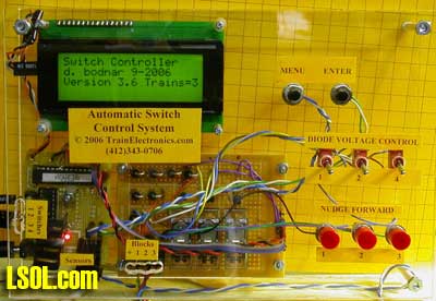 All of the external connections are in the lower left. Switches connect to the left. Under the word "Sensors" is the telephone cable that goes to the sensors. The block power cables are under "Blocks + 1 2 3".
Accessory Receiver The connection on the schematic that is labeled "END switch / Sound 1 or Sound 2 on receiver" is the one that goes to the radio control accessory receiver, pictured below. This item is normally used to activate sound, lights or switches with the Train Engineer hand-held radio control unit. When properly configured pressing one of the accessory buttons on the transmitter activates the "END" switch on the controller. In this photo it is temporarily connected to a switch motor for testing. 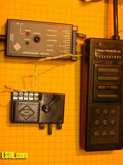
Operation When first powered up the display shows copyright and version information. It then resets all of the switches and checks that all sensors are blocked by engines. If it finds that a sensor is not blocked it briefly applies power to the appropriate block moving the engine into position. This repeats till all sensors are blocked. Once all of the engines are seen to be in position the user is asked to press ENTER to begin. At this point the engines leave and progress through the layout as previously described. One after the other one engine exits as the other two wait their turns. 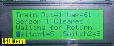
Two Trains or Three? You may notice that the display in one photo shows "Trains = 3". The layout that is controlled by this system is actually made up of two independent loops, one with two trains and two sidings and the other with three trains and sidings. Rather than make up two different systems, one for two and one for three trains, I chose to make two identical units. Either of them can be configured in software to control two trains or three. Even though a two train controller would have been much simpler to construct, in the long run it is easier to maintain only one design and one software revision.
Conclusion As you can see this was something of an epic project to build and document. I hope that some or all of it was of interest to you and can be incorporated into your layout. Why Not DCC? A few LSOL readers asked me why I hadn't chosen to use DCC (Digital Command Control) to automate this layout. There are a number of reasons but the main one is that the layout's owner didn't want DCC. Other reasons for not using DCC for this project include: - Cost - In addition to basic DCC equipment one would also need to purchase DCC units to detect train position and to control turnouts
- Control & software - to meet the design specifications for this system a DCC controller would need to be hooked up to a laptop or other computer and software would need to be purchased (or written). Programming would still need to be done to automate the train operation.
- An individual controller would need to be installed in each engine.
Stay tuned... I have really gotten used to adding "Stay Tuned..." to the end of each of these articles so I think I'll do it one more time so I can give a little peek at my next train automation project. Maybe There is Room for a Bit of DCC After All... In spite of what I said above about DCC it is an interesting technology and there are some advantages to using it. This is especially true if one can utilize a custom made DCC control system. Over the last few months I have built a few DCC controllers and am close to finishing up a PIC based control unit that duplicates much of what the controller described in this series can do. 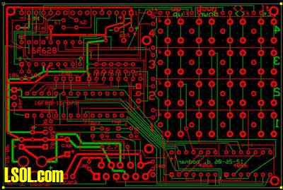
There are still a lot of things to work out but you may see an article soon. Stay tuned...
| Picaxe info |
| Hi Dave, Because of the way LSOL implements their password entry, I cannot get to your articles on the PicAxe. I have volunteered to build a controller for our Christmas display which could really benefit from the use of this controller. Would you be able to send me info .... or a link other than LSOL .... to info on the use of this chip. I sure would appreciate it. It has been a bunch of years since I have done assembly level programming! Thanks in advance! Dusty |
| Dusty Suit from Silver spring, MD - 10/02/2008 - 17:01 |
Top of Page
|