Power, Sound, R/C
:
Remote Control
Aristo TE in an LGB Mogul
Mar 28, 2007


By Rick Taylor |
Author
Bio
Well, I have just completed installing an Aristo-Craft 75 Mhz on-board receiver (CRE55491) into my LGB 2-6-0 Mogul.
|
Well, I have just completed installing an Aristo-Craft 75 Mhz on-board receiver (CRE55491) into my LGB 2-6-0 Mogul. It was an interesting project, so I thought I would write a quick article explaining my approach to the installation. I decided to go with the Aristo on-board control for several reasons. One of those reasons being that the Aristo-Craft TE transmitter cost is less than others and I wanted to have 3 transmitters on my layout so that my nieces kids can come over and each control a train. And of course, I need a transmitter so I can hit Emergency Stop when needed! :) So, like any fun project, I was off to the Hobby Shop to pick up the 75 Mhz TE transmitter and on-board receiver. While there, I also picked up the Aristo-Craft Elite 22 volt 13 amps (CRE55464) power supply. Ya gotta love walking into the Hobby Shop! Next was the project itself. I quickly decided that the garage was too HOT for this project, so I decided to work on the family room bar (Debbie wasn't real happy, but she's a great sport when it comes to my train obsession). Here is the proper Tucson summer time model train-working environment: INSIDE with Air Conditioning. :) 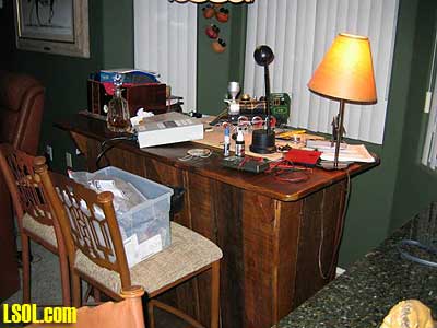
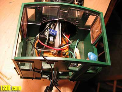
Here is the approach I took to disassemble the LGB Mogul: Remove the Engine Cabin Roof (1 screw in back and 2 in front). Remove the Cabin Boiler structure (4 screws under the Cabin). There are plastic cylinders glued directly underneath the cabin and I had to remove those also. The glue was soft, so I just wiggled the cylinders off. As seen in the next photo the LGB engine control Printed Circuit Board (PCB) is exposed. You can also see where several years ago I had added 2 LEDs to light up the cabin: one is a red LED (that glows through holes I had drilled in the boiler door) and the second is a bright white LED that shines up into the face of Engineer "Bob"! 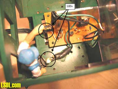 Slide the (green) cabin structure back away from the boiler as seen in the photo below (there are brass rods that run the length of the boiler and will slide out of the holding stanchions. You can remove the brass rods as they are only pressed into the plastic cabin structure. The LGB engine control printed circuit board will have 4 wires (brown and black for the front head light, white and black for the smoke unit) running to the front of the engine. There is a ribbon cable with 3 wires (white, brown green) coming from underneath the circuit board and running to the plastic engine block. 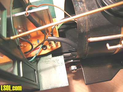
Remove the Engine Boiler (remove 2 very small screws underneath and disconnect or unplug the two brass rods connecting the boiler to the front cattle guard) 
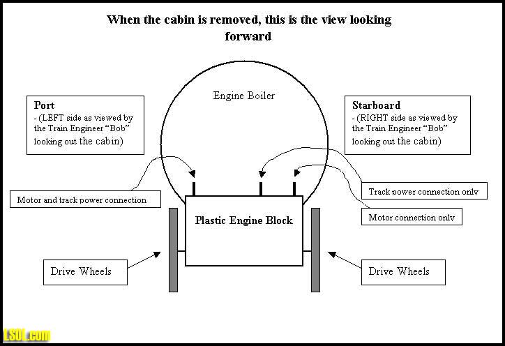
CLICK FOR LARGE PICTURE As seen in the picture below, all of the wiring is exposed (the circuit board sitting on top of the note book is the 75 Mhz on-board receiver). 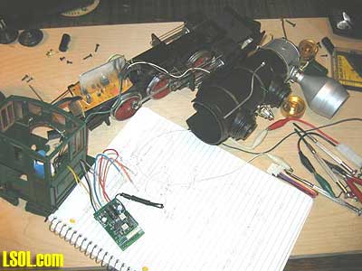 With an ohmmeter I discovered that LGB wired one of the track power pickup leads to one of the motor leads. That is why there are only 3 wires coming from the plastic motor block unit instead of the 4 wires, which I had expected.
The Aristo on-board receiver REQUIRES that you have 2 wires for track power pickup (or battery power) and 2 wires for the motor drive. They CANNOT be connected in any way. The motor and track power must be isolated. Aristo says the on-board receiver would be damaged if we keep the common motor and track power lead. So, I had to go into the motor block and see if I could separate the common motor and track power connection. Remove the top of the Motor Block (remove 4 long screws and 2 smaller screws. The smaller screws attach to lead weights in the Motor Block) The photo below shows the Motor Block with the top off uncovering the motor, connection posts, and gears. Notice the RED tab on the motor to the left side of the picture (if this is not in color it is the left side of the motor next to the single connection post). That single connection post is our problem child because it connects the port side track power and motor together (port: is left side as viewed from the train engineer looking into the cabin looking forward). This is a physical contact connection made by the motor resting on the post, not a wire that we can cut and splice into. 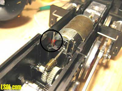
My solution was to remove the motor (simply pull the motor up and out from the plastic motor block housing), bend the port side (red tab) motor contact in half so that it would not make contact with the wiring post and then solder a wire to that bent motor contact as seen here. Make sure that you have bent or cut the motor contact short enough so that it does not touch the port side motor block contact post. 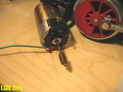 I then drilled a small hole in the motor block cover and ran my wire (green) out the top through the hole. 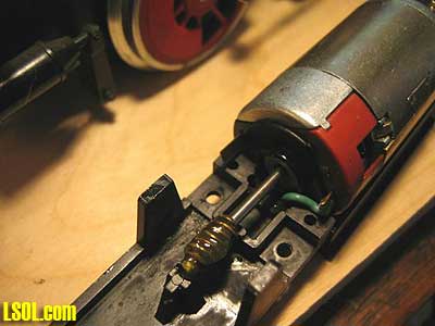
Here is the motor block cover sitting upside down with the wire pulled through the hole and the motor sitting in place. I then installed the motor block cover and motor back in place all at one time. Putting the motor in place and then trying to install the motor block cover did not work for me. The wire kept getting in the way of the installation.
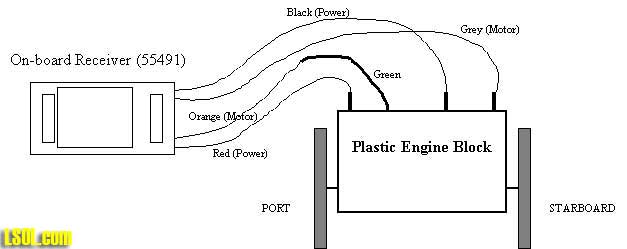
This picture shows the reassembled motor block with the new green wire, which is attached to the port side motor connection. 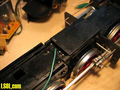 Now I can wire the motor and track power independently to the On-board Receiver. Below is the description of how to connect the on-board receiver and the motor block. - Track Power: I connected the port side track-power (which is the existing motor block post that we just isolated) to the Red, wire #7 called "Left Side Track Power Pick-up" in the manual. Then connected the starboard side track-power to the Black, wire #1 called "Right Side Track Power Pick-up". - Motor: I connected the new Green wire coming out of the motor block (which is our port side motor connection) to the Orange, wire #6 called "Left Side Motor Terminal". Then connected the starboard side motor to the Grey, wire#2 called "Right Side Motor Terminal". 
CLICK FOR LARGE PICTURE
Lights: I would recommend that you go to the Aristo-Craft web site and download the TE manual if you are going to connect lights to the on-board receiver. The manual on the web page is called "Updated Instruction Manual for On-Board Train Engineer - CRE-55492" and once downloaded it's called "te75manual.PDF". (The 55492 is Aristo's 55003 TE Transmitter and 55491 On-board Receiver packaged together). The small manual supplied with the receiver has a totally different way to connect the lights with diodes. That method not only does not work, but it is more difficult to wire. The PDF manual has the proper light installation solution. Just connect the lights to the front and rear light connections (if LEDs include a series 1K ohm resistor for each LED) with the returns connected to the "common" wire. No diodes, no cutting into track power. I left the original LGB printed circuit board (PCB) in the cabin to control all the LED lights and smoke device. There is a switch at the rear of the Mogul with three positions. Position (1) turns everything off (ie. no motor, no lights, no smoke), (2) turns on motor and lights with no smoke, (3) turns on motor, lights and smoke. When the smoke element is turned on, with switch position 3, the LGB PCB gets rather warm. Since my on-board receiver was going to be positioned on top of this board (as seen in the next photo.) I did not want all the heat, so I moved the switch to position number 2 (motor, lights, no smoke). I will turn to switch position 3 when I want smoke, but I usually run without smoke anyway.
 Red Push Button: There is a push-button switch required for programming the 55491 receivers. It is supplied with a connector for easy removal, but it stands up rather high. In order to get the on-board receiver in to the Moguls boiler area I had to cut the connector from the push-button and solder the wires directly to the receiver's circuit board. It is a snug fit. Programming Lights: Since I did not use the receiver to control the engines lights I needed to connect a light to one (front or rear) of the on-board receiver light controls. The receiver is setup to blink the train lights during programming. So connected a yellow LED with a 1 K ohm resistor to the "Rear Headlight" control and the "common" of the receiver. That way, I could see the blinking rate of the LED while programming, it would not be on while the engine is moving forward and when it came on while moving backward it would be a low intensity light and look nice. Antenna: Wiring the antenna was another interesting effort. You do not want the wires of the antenna to cross over top of each other or you effectively shorten the antenna's receive wavelength, which in turn reduces your reception capabilities. Hence, you will have to be closer to the engine than normal. So I cut a piece of styrene to wrap the antenna wire around (staggered with out crossing over itself) and mount to the roof of the engine cabin. Figure 10 shows the notches I cut and how I wrapped the wire. I also made sure that the wire leading from the boiler to the antenna did not cross.
This arrangement seems to work pretty well. With the TE transmitter antenna in the collapsed position I can control the engine at about 30 feet. With the antenna pulled out, I can control the engine from all over my yard, which the longest run is about 90 feet. I have ordered some small 75 Mhz antennas from www.ecubedrc.com for $10 each. These new antennas boast some very good reception numbers and are only 3 inches long. When I get one installed I will let you all know how they work out. 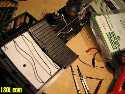 Well, that pretty much wraps up my LGB Mogul on-board receiver project. It's always fun digging into the guts of these train products and seeing how they are constructed. LGB seems to be Tops when it comes to a quality design. Top of Page
|