Power, Sound, R/C
:
Remote Control
Aristo Revolution Auxiliary Outputs Exposed
Nov 24, 2010


By Dave Bodnar |
Author
Bio
The Aristo Craft Revolution receiver has six auxiliary output pins that are normally used to control a sound card or an external smoke unit. Recently I have received a number of emails from model railroaders who are interested in using the auxiliary outputs to directly control lights, a relay or some other electronic / electrical device. All of these things can be done with these outputs if you connect them properly.
|
The Aristo Craft Revolution receiver has six auxiliary output pins that are normally used to control a sound card or an external smoke unit. Recently I have received a number of emails from model railroaders who are interested in using the auxiliary outputs to directly control lights, a relay or some other electronic / electrical device. All of these things can be done with these outputs if you connect them properly. Auxiliary Output Pins There is a seven pin header on Revolution receivers that is labeled "AUX OUT". Its pins are labeled "ABCDEF COM". 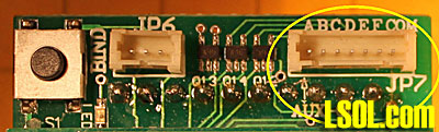
The cable that plugs into this header has seven wires colored black , brown, red, orange, yellow, green and blue. The black wire is the common or ground connection. The other wires correspond to outputs 1 through 6 and can be activated by pressing one of the buttons labeled 1 through 6 on the Revolution transmitter. 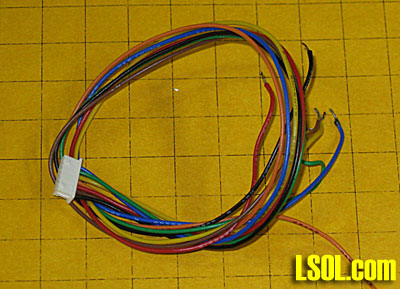
Open Collector Outputs The Revolutions receiver outputs are referred to as open collector outputs. This means that electronically they are equivalent to NPN transistors. The control lead from the wiring harness is connected to the collector of a transistor whose emitter is attached to ground. When an auxiliary output is activated on the Revolution the control lead connects the output device to ground. This design works well but is limited by the amount of power that it can handle. The devices that connect to the outputs are seen at the left of this photo. 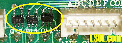 Note the "2X" markings on them. This was the only clue that I had to their identity.... it was great fun getting the data sheet for them! The devices on the receiver are dual chip transistors, similar to part # SUR521H. According to the data sheet each of the transistors is rated at 100 ma. I would not, however, connect a device that would draw anything near that level. It is best to keep the current draw to 20 or 30 ma, maximum.
Testing the Auxiliary Outputs The simplest way to test the outputs is to connect each of them to an LED that can be turned on and off by the Revolution transmitter. This schematic shows the wiring that is needed to connect to six LEDs to the six outputs. The ground connection, which goes to the COM terminal, should attach to the negative terminal of a 12 volt battery or power supply. The connection labeled +12v goes to the positive terminal of the power source. Each of the cathodes from the LEDs connects to the interface through a 1000 ohm current limiting resistor. All of the anodes are wired together and connected to positive 12 volts. (There is detailed information about LEDs and there use in another article, see LEDs 101) 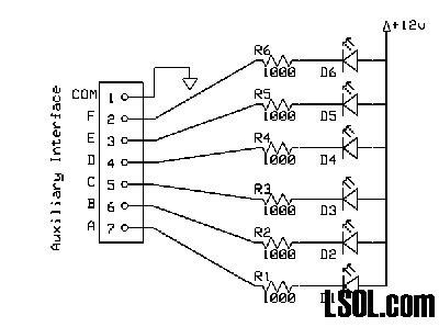
Click for Larger Image
The photo shows the circuit above on a simple breadboard. The seven wires from the auxiliary interface plug into the breadboard with the black wire going to the negative buss and the colored leads going to the LEDs through six 1000 ohm resistors. The Revolution and the breadboard share the same power supply. The power cable going to the breadboard, the red and black twisted wires, is connected in parallel with the power wires that go to the Revolution. 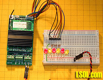
Activating a Relay If we had a relay that drew no more current than the LEDs used above we could just substitute relays for the LEDs and be done. Unfortunately things are not that simple. To activate a relay we need to deal with several things. - A transistor must be added to each output to deal with the increased current drawn by relays
- Each relay must have a diode across the relay coil to protect the transistor from voltage spikes
- We must provide an appropriate voltage to the relay which may or may not operate from the voltage that we are applying to the Revolution's track pickups or from our battery
The circuit shown in the schematic below includes the components that are needed to operate a relay. Q1 is a general purpose PNP transistor. I used a 2N3906 but many others would work, too, The base of the transistor connects to one of the auxiliary outputs through a 1K resistor. The emitter connects to the power that is being applied to the Revolution receiver. Resistor R2 provides bias voltage to the transistor's base. Diode D1 protects the transistor from voltage spikes that are created when the magnetic field in the relay's coil collapses. The circuit will work without the diode but the transistor will fail after a short time if the diode is omitted. Resistor R3 limits the amount of current that goes to the relay. If we are using a 12 volt relay and supply 20 volts to the Revolution we have to use an appropriate resistor to protect the relay. I used a 470 ohm resistor. This value was determined by measuring the current drawn by the relay when it operated at 12 volts. A 470 ohm resistor limited the current to the same value at 20 volts.
Adding a resistor is the simplest way to deal with using a relay with a coil that requires a lower voltage than what you have available but it may not be the best way. Calculating the appropriate resistor value can be a challenge and the resistor can get quite hot when the relay is active. A better alternative is discussed below. 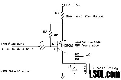
Click for Larger Image
This photo shows the relay, the blue object to the right, the transistor, the small black device at the center of the board, the diode and the resistors that complete the circuit. This relay is connected to the LED that is activated by switch number 1. That is the one activated by the blue wire from the auxiliary connection. Five more relays could be added to the circuit by duplicating the same circuitry that is used here. 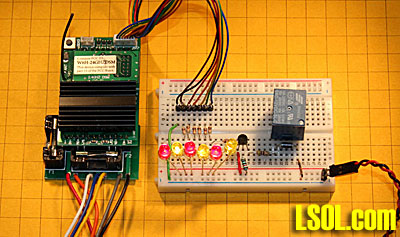
Adding a Voltage Regulator A better way to lower the voltage that goes to the relay is to use a voltage regulator. If we are supplying 20 volts to the Revolution and we are using a 12 volt relay a 12 volt regulator such as a 7812 does a great job of providing the right voltage. Similarly a 7805 regulator can be used to supply 5 volts to a 5 volt relay. The regulator may get hot, too, but it is designed to dissipate heat and a heat sink can easily be added should it be needed. 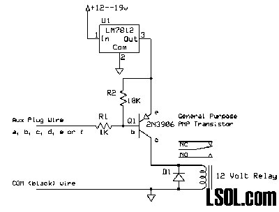
Click for Larger Image
Here is the breadboarded example. The voltage regulator, on the far right, takes the input power and delivers 12 volts to the board. Note that the 470 ohm resistor that once went from the transistor to the relay has been replaced by a yellow piece of wire as the resistor is no longer needed. 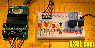
This close-up shows the connections to the 7812. The terminal to the left receives the input voltage from the track or batteries. The center terminal connects to ground. 12 volts is available at the terminal on the right and is connected to the positive terminal on the breadboard through the yellow wire at the right. 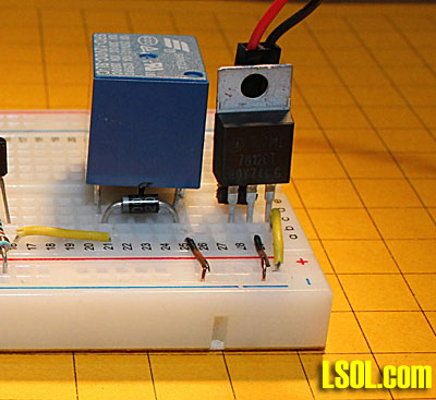
Give it a Try! I hope that this overview of the auxiliary interface on the Revolution receiver provides you with enough information to experiment yourself. Keep in mind that the same circuits can be used to activate relays with the auxiliary output ports that are on many other radio control or DCC decoders. Most of them also use an open collector design. Please let me know if you have any questions. |