Power, Sound, R/C
:
Remote Control
AC Power Trolley Modification
Jan 13, 2012


By David Bodnar |
Author
Bio
The original design objective for the PICAXE based speed controller was for it to be used as a track side power controller that would operate DC track powered trains. Come learn see how this new modification will give your railroad more realistic operation.
|
 Introduction
The original design objective for the PICAXE based speed controller (see: PICAXE Model Railroad Speed Controller with VIDEO ) was for it to be used as a track side power controller that would operate DC track powered trains. One of the modes that it supports is point-to-point operation where a train or trolley goes back and forth on a single length of track. Under normal DC track power operation the controller turns on the track power for a set time (adjustable with the TV remote) and the train goes from one end of the track to the other. Diodes are installed in cut sections of track at each end and oriented in such a way that the train stops when it is going into the cut section. After the time expires the controller reverses the current on the track, the diodes begin to conduct and the train reverses and repeats its trip to the other end of the track. This repeats over and over again. There are a few problems with this mode that include: 1. When the trolley is at either end of the point-to-point power is completely removed and any lights that may have been on are extinguished
2. When the power to the trolley is reversed and it is ready to start up again it is not uncommon for a bit of dirt on the track or wheels to keep power from going to the wheels and the train fails to start.
3. Power is also removed from any sound devices when the trolley sits at the ends rendering it silent. These shortcomings can be overcome by placing the controller inside of the trolley and applying fairly high voltage AC power to the track.
In order to use the controller in this manner the circuit needs to be modified. The modification is composed of a bridge rectifier, filter capacitor and a device to detect when the trolley enters one of the ends of the track. The bridge rectifier should be able to handle the maximum current that your trolley will draw, up to 3 amps. The capacitor, C2, is shown as a 2000 mfd electrolytic. Any value from about 1000 mfd and up rated at no less than 25 volts should work. I like to use capacitors that are rated at double the operating voltage so I wired three 680 mfd / 50 volt caps in parallel giving me about 2000 mfd @ 50 volts. The photo below shows the 3 capacitors and a bridge rectifier that I made up from 4 discrete diodes, a good alternative if you don't have a bridge rectifier on hand. This small circuit board also has the optoisolator and related components on it as I used this as a test unit before I installed the optoisolator on the circuit board as shown below. 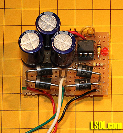 This photo shows a different style bridge rectifier and two capacitors on top of it. The two caps are 2200 uF 16 volt units. They are wired in series giving about 1000 uF at 32 volts. The green/white wires go to the track power pickups and to the bridge rectifier as well as to the input pins for the optoisolator circuit. The red/black wires deliver DC voltage to the PICAXE board. 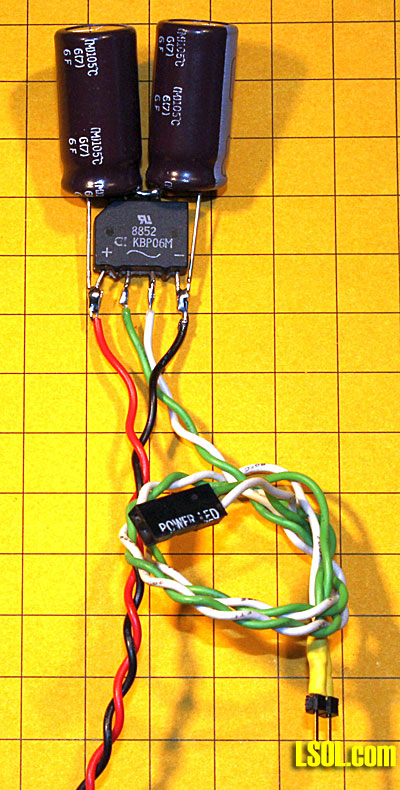 In this snippet of the complete schematic the bridge rectifier and capacitor are to the left and the optoisolator and its associated parts are on the right. Note that this part of the circuit is wired to the AC side of the bridge rectifier. When full wave AC is available the optoisolator is on and pin 10 on the PICAXE sees 5 volts. When the trolley enters one of the ends of the track diodes D5 or D12 partially rectify the AC turning it into 1/2 wave AC. When this happens the optoisolator turns off and the PICAXE sees zero volts on pin 10 and the program instructs it to stop. 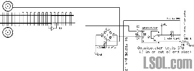
Click for Large Image
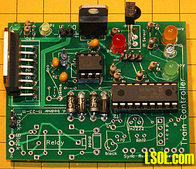
Wiring the Circuit
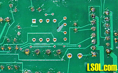
Start by building the circuit as described here: PICAXE Model Railroad Speed Controller with VIDEO The optoisolator will be installed in the space that is normally used for the memory chip that is covered in this article: PICAXE Model Railroad Speed Controller Train Activity Recorder with VIDEO A six pin socket fits into the front six holes where the eight pin memory socket would normally be mounted. If you don't have a six pin socket on hand you can just cut one from an eight pin or larger socket as I have done. 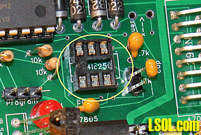 A number of traces on the circuit board need to be cut before installing the parts for the modification. I use a fine drill bit in a Dremel tool to cut traces but a sharp knife or razor blade will work, too. Just make sure that you go clear through the trace. If in doubt check with an ohm meter. Three traces need to be cut on the top of the board, they are marked in this photo... 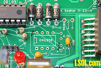 ... and shown cut here. 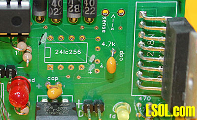
Here is the trace that needs to be cut on the back of the board. 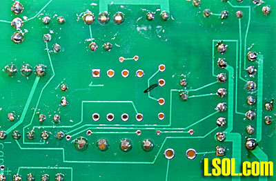
The schematic shows the new components that are added in the upper right area. The input to the optoisolator comes directly from the track pickups. The output from the optoisolator goes to pin 10 on the PICAXE. Be sure to orient the diodes as shown in the drawing. They are NOT installed in the same manner as with a DC point-to-point where both diodes go in the same direction. 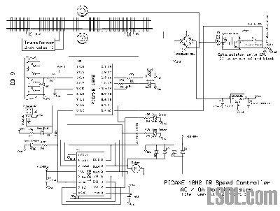
Click for Large Image Here are the parts that are needed for this modification. A six pin socket, a 4N27, a 100K resistor, a 1K resistor, a small diode and a 1 Mfd tantalum capacitor. The bridge rectifier and capacitor are not shown in this photo. 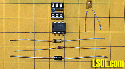
Adding the Modification
Start by inserting the tantalum capacitor through the two holes shown here. Note that you DO NOT need to solder the capacitor to these holes. The capacitor's positive lead is towards the bottom in the photo. 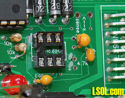
Pull the leads through the back of the board but don't cut them off. 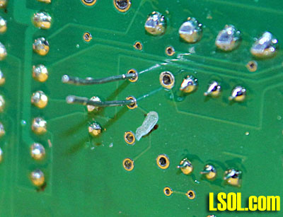 Bend the leads over and solder as shown. Take care that the top lead does not come in contact with the hole under the lead. 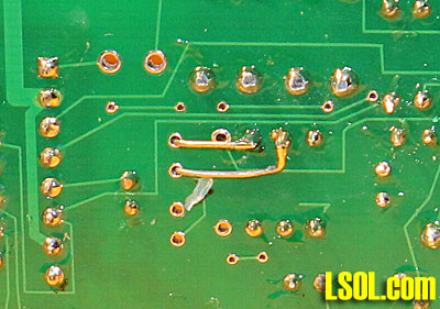
Solder a small scrap lead from an LED as shown here. 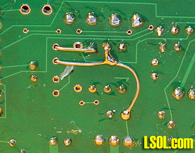
Insert the two pin header as shown here. Solder from the back. 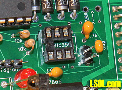
Add the 100K resistor. 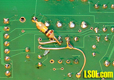
Then the 1K resistor and the diode. Note the orientation of the diode. Its band must point as shown. 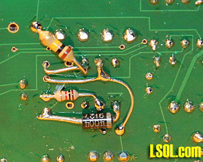
Here is a close-up of the finished modification. 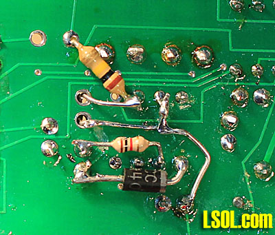 Insert the 4N27 with the notch pointing away from the L298N. 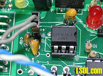 Here is the completed board.
Testing
This short program can be used to test the circuit. Run the program and note the serial window that should show a continuous display of Pin 10 = 0 'd. bodnar - 12-15-2011
' AC 1/2 wave test
#PICAXE 18M2
#TERMINAL 4800
#NO_DATA
Symbol HalfAC = pinb.4 'pin 10 ' value=1 if full wave =0 if 1/2 wave
Symbol LEDBlue = c.7 'pin 16
TestPin10:
sertxd("pin 10 = ",#halfac,13,10)
if halfac=1 then
high LEDBlue
else
low LEDBlue
endif
goto testPin10:
Apply a DC voltage to the pins next to the 4N27. When applied in one way the Pin 10 = 0 will continue, when switched + for - it should change to Pin 10 = 1. In addition the blue LED will light when pin 10 = 1. 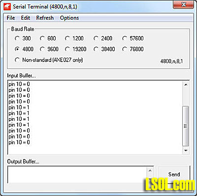
Installation
To install the unit in a trolley or locomotive you must isolate the wires that go to the wheels / track and those that go to the motor(s). The locomotive that I used for testing is shown below. It has two powered trucks and two sets of track pickups. I wired the motor leads in parallel making sure that the wheels turned in the same direction when I applied power. I did the same with the wheel pickup wires, again making sure that I connected the wheels so the all wheels on one side were wired together. In this photo the red/black wires go to the track pickups and the orange/white wires go to the motors. 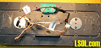 Connect the wheel pickup wires to the AC inputs on your bridge rectifier. These leads are generally marked with a symbol that looks like an "S" laying on its side. The output from the bridge rectifier is marked with a "+" for positive and a "-" for negative. You will also need to wire an electrolytic capacitor in parallel with the output making sure that you connect positive to positive and negative to negative. In this photo I was experimenting with various capacitor values using capacitors with clip leads to expedite testing. Make sure the voltage of the capacitor is at least 25 volts. The higher the microfarad rating the better. The cap shown here is 4700uF with a voltage rating of 25 volts. Its negative lead is marked with a silver line. The red/black wires will go to the power input pins on the PICAXE controller. One set of the green/white wires go to the track pickups. The other set of green/white go to the input to the optoisolator. 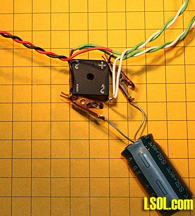 Here the PICAXE board and bridge rectifier/capacitor have been mounted temporally on the test locomotive. Place the locomotive on a track with diodes at each end with their bands pointing outwards, as shown in the schematic. Apply AC power to the track. I used an old Lionel transformer and applied about 15 volts AC. I have tested the circuit with up to 20 volts AC. Speed up the train with the TV remote control. When the locomotive reaches the diode section of track it should decelerate / stop / reverse and continue on its way. If it does not reverse the plug from the track power that goes to the optoisolator input pins and make sure the diodes are oriented properly on the track. 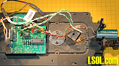 Conclusion
Every holiday season I run a trolley on a track on the railing in front of my house. During the 2011 holidays the trolley equipped with this modified controller ran flawlessly for 32 days, running up to 16 hours a day. It did not skip a beat, going back & forth more than 150 times each hour! I was looking for a good reliable system to run my holiday trolley and I think I have found it!
Latest and Greatest Control Program
The software shown here has been modified from the main program to support reversing when 1/2 wave AC is detected. The areas that have been modified for the 1/2 wave AC detection circuit are highlighted in the program listing below. 'd. bodnar - 11-27-2011 v6.3B
' board revised to sense AC 1/2 wave
' for auto-reverse on front porch @ Christmas
#PICAXE 18M2
#TERMINAL 4800
#NO_DATA
Symbol Direction1 = b.5 'pin 11 - one high & one low - swap to change direction-if = fast motor stop
Symbol Direction2 = b.0 'pin 6 - one high & one low - swap to change direction
Symbol Motor = b.3 'pin 9 - PWM output for motor speed
Symbol IRSense = b.2 'pin 8
Symbol Aux1 = c.2 'pin 1 - can be used for current sensing - OR OTHER PURPOSES!
Symbol Aux4 = c.5 'pin 4 input only
Symbol Aux17 = c.0 'pin 17
Symbol Aux18 = c.1 'pin 18
Symbol LEDAmber = c.6 'pin 15
Symbol LEDBlue = c.7 'pin 16
Symbol HalfAC = pinb.4 'pin 10 ' value=1 if full wave =0 if 1/2 wave
Symbol InfraRED = b27 'store IR value
symbol Digit = b26 'Flash Value
symbol Value = b25 'Flash Value & Version
Symbol ValueTemp = b24 'Flash Value
symbol divisor = b23 'Flash Value
symbol temp5 = b22 'Flash Value & GetRndOnce
symbol temp = b21 'Flash Value & Version
Symbol CruiseTime = b20 'Time to run before reversing
symbol digitsbyte = b19 'Get number routine
Symbol TempByte = b18 'Flash Value & Version & Get IR Num
Symbol WaitTime = b17 'pause before reverse
Symbol ADRate = b16 'accel / decel rate
Symbol DecelTime = b15 'point where decel beings on p-2-p
Symbol RndmWait = b14 'RANDOM - needed?
Symbol TempWord = w5 'RANDOM - needed?
Symbol Loopie0 = w4 'Decel & Random
Symbol MinSpeed = w3
Symbol SetSpeed = w2
Symbol DecelFlag = Bit0 '=1 if decel time has caused deceleration otherwise =0
Symbol FwdBkwFlag = Bit1 '=1 if forwrad / =0 if backward
Symbol SlowDnFlag = Bit2 '=0 if no slow down point set, =1 if set
Symbol Decel2Zero = Bit3 '=1 if we want deceleration to zero, not minimum speed
'Also Using
'Memory 30 for Decel loop start value (word)
'Memory 32 for Decel loop end value (word)
'Memory 34 for time temp storage (byte)
Symbol LStart = 0'120'450
Symbol TTrigger = 7000
Symbol Period = 150
Symbol PWMMax = 1023'600
Symbol ChUp = 16
Symbol ChDown = 17
Symbol VolUp = 18
Symbol VolDown = 19
Symbol OK = 20
Symbol Retrn = 59
Symbol One = 0
Symbol Two = 1
Symbol Three = 2
Symbol Four = 3
Symbol Five = 4
Symbol Six = 5
Symbol Seven = 6
Symbol Eight = 7
Symbol Nine = 8
Symbol Zero = 9
Symbol Power = 21
Symbol MENU = 96
Symbol VChip = 14
Symbol Exxit = 99
Symbol VerWhole = 6
Symbol VerDecimal = 3
high direction1:low direction2
VeryTop:
Read 0, WORD SetSpeed 'read variables from memory
Read 2, WORD MinSpeed
Read 4, WaitTime
Read 5, ADRate
Read 6, DecelTime
Read 7, RndmWait
Read 8, slowdnflag
if DecelTime=0 then
DecelTime=WaitTime
endif
decelflag=0
if deceltime <> waittime then
decelflag=1
slowdnflag=1
endif
pwmout motor,50,500' set pwm duty
pwmduty motor, 0
Pause 500
sertxd("d. bodnar",13,10,"11-29-2011 v6.3B AC Trolley",13,10,13,10) '4800 baud @ this clock speed
'Test12: sertxd("pin 12 ",#halfac,13,10):goto test12:
;Routine to flash out version number of software
for tempbyte=1 to VerWhole:high LEDBlue:pause 150:low LEDBlue:pause 150:next tempbyte:pause 400
temp=verdecimal
IF temp > 0 then
for tempbyte=1 to VerDecimal:high LEDBlue:pause 150:low LEDBlue:pause 150:next tempbyte
else
high ledblue:pause 10:low ledblue
endif
Pause 1000
GOSUB ShowReadValues
gosub accel
time=0
Cruise:
if HalfAC = 0 then 'value=1 if full wave =0 if 1/2 wave
sertxd("1/2 wave detected",13,10)
if fwdbkwflag=0 then
FwdBkwFlag=1
goto revers
else
FwdBkwFlag=0
goto revers
endif
endif
'sertxd("pin 12 ",#halfac,13,10)
Random TempWord
if time <=2 then gosub GetRndOnce
'Routine to show time that has passed on Terminal
PEEK 34, TempByte
if time>254 then
time=0
endif
if time <> TempByte then
sertxd("t=",#time," ")
POKE 34, time
toggle ledamber
endif
'if no auto-reverse (waittime) has been set don't reverse or decel
if waittime=0 then
goto SkipReverse
endif
'Slow down to minspeed if decel point has been set - do it only once via decelflag
if time >= DecelTime and decelflag =0 and DecelTime<>CruiseTime then
sertxd("@deceltime ",#deceltime," f ",#decelflag,13,10)
gosub DecelSet2Min
DecelFlag=1
endif
'Run time has expired - bring to complete stop & reverse
if time >=CruiseTime then
sertxd("Time= ",#time,13,10)
time=0
decelflag=0
goto Revers
endif
SkipReverse:
'Get IR input and act on it
{Infrared=255
Irin [1, Cruise],IrSense, InfraRED
sertxd("IR= ",#infrared," ")
if InfraRED = Power then 'use POWER button to set deleration poing
DecelTime=time
SlowDnFlag=1
Write 6, DecelTime
Write 8, Slowdnflag
gosub ShowReadValues
endif
if InfraRED = OK then 'Mute on Westinghouse Remote - hit it to set minimum speed
MinSpeed=SetSpeed
Write 2, word MinSpeed
Write 8, Slowdnflag
gosub ShowReadValues
endif
if InfraRED = Retrn then GetOption 'after RETURN button choose 1-->4 to set options
if InfraRED = VolUp and FwdBkwFlag =0 then ' VOLUME UP and DOWN to change direction
FwdBkwFlag = 1
goto revers
endif
if InfraRED=VolDown and FwdBkwFlag =1 then ' VOLUME UP and DOWN to change direction
FwdBkwFlag = 0
goto revers
endif
if InfraRed = MENU then 'press MENU to pause & save speed or to restart after pausing
Sertxd("@ MENU",13,10)
if SetSpeed > 0 then
POKE 30,WORD SetSpeed
if MinSpeed <> 0 then
Decel2Zero=1
endif
gosub decel
SetSpeed=0
disabletime
pause 1000
else
PEEK 30, WORD SetSpeed
gosub accel
enabletime
endif
endif
if InfraRED=ChUp then 'CHANNEL UP and DOWN to speed up or down
high LEDBlue
SetSpeed = SetSpeed +5
pwmduty motor,SetSpeed
write 0, WORD SetSpeed
Write 8, Slowdnflag
sertxd(#setspeed,13,10)
else
low LEDBlue
endif
if InfraRED=ChDown then 'CHANNEL UP and DOWN to speed up or down
high LEDBlue
if SetSpeed > 5 then
SetSpeed = SetSpeed -5
sertxd(#setspeed,13,10)
endif
pwmduty motor,SetSpeed
write 0, WORD SetSpeed
Write 8, Slowdnflag
else
low LEDBlue
endif}
goto Cruise:
{
GetRndOnce: 'Put time to run train into Temp
Random TempWord
loopie0=65535/rndmwait
Temp5=tempword/loopie0
CruiseTime=WaitTime+temp5
return
GetOption:
pwmduty motor,0 ; STOP
sertxd("@GetO",13,10)
pause 1000
StayHere2:
Infrared=255
Irin [1, StayHere2],IrSense, InfraRED
sertxd("IR= ",#infrared," ")
if infrared = VChip then
goto ReadyReset:
endif
if infrared >4 then 'only accepts number buttons 1-->4
goto cruise
endif
Branch infrared, (speedmax, speedmin, runtime, acceldecelrate, RndmSetting)
goto cruise
RndmSetting:
value = RndmWait
gosub flashvalue
gosub getirnumber
RndmWait=digitsbyte
sertxd("RndmWait= ",#RndmWait,13,10)
write 7, RndmWait
Write 8, Slowdnflag
gosub ShowReadValues
gosub accel
goto cruise:
speedmax:
value = setspeed
gosub flashvalue
gosub getirnumber
setspeed=digitsbyte
sertxd("max= ",#setspeed,13,10)
write 0, word setspeed
Write 8, Slowdnflag
gosub ShowReadValues
gosub accel
goto cruise:
speedmin:
value = minspeed
gosub flashvalue
gosub getirnumber
minspeed=digitsbyte
sertxd("min= ",#minspeed,13,10)
write 2, word MinSpeed
gosub ShowReadValues
gosub accel
goto cruise:
runtime:
value = waittime
gosub flashvalue
gosub getirnumber
waittime=digitsbyte
write 4, WaitTime
Write 8, Slowdnflag
sertxd("wait= ",#waittime,13,10)
time=0
if DecelTime=0 then
DecelTime=WaitTime
endif
gosub ShowReadValues
gosub accel
goto cruise:
acceldecelrate:
value = adrate
gosub flashvalue
gosub getirnumber
adrate=digitsbyte
write 5, adrate
Write 8, Slowdnflag
gosub ShowReadValues
sertxd("ad= ",#adrate,13,10)
goto cruise:
ReadyReset:
Infrared=255
Irin [1, ReadyReset],IrSense, InfraRED
if infrared = Exxit then DoIt
if infrared = Power then Cruise
goto readyreset
DoIt:
deceltime=0:setspeed=0:minspeed=0:waittime=0:adrate=0:RndmWait=0:slowdnflag=0
Write 0, WORD SetSpeed
Write 2, WORD MinSpeed
Write 4, WaitTime
Write 5, ADRate
Write 6, DecelTime
Write 7, RndmWait
Write 8, slowdnflag
goto VeryTop:
AutoReverse:
for b0=1 to 10:toggle IrSense:pause 100:next b0
goto cruise}
Revers:
sertxd("@Revers",13,10)
Decel2Zero=1
gosub decel
pause 1000
toggle direction1:toggle direction2
gosub accel
WaitHere:
if HalfAC=0 then WaitHere: 'stay here till out of diode end
goto Cruise:
Accel:
disabletime
sertxd("@Accel",13,10)
for loopie0= 0 to SetSpeed step 5
sertxd(#loopie0," ")
pwmduty motor,loopie0 ; set pwm duty
toggle ledblue
pause adrate
next loopie0
sertxd(13,10)
enabletime
return
Decel:
disabletime
sertxd("@Decel",13,10)
if decelflag=1 then
return
endif
if SlowDnFlag=1 then
for loopie0=minspeed to 0 step -3
gosub DecelLoop:
next loopie0
goto skip0:
endif
if Decel2Zero=1 then
Decel2Zero=0
for loopie0=setspeed to 0 step-3
gosub DecelLoop:
next loopie0
goto skip0:
endif
DecelSet2Min:
sertxd("@DecelSet2Min",13,10)
for loopie0= SetSpeed to MinSpeed step -5
gosub DecelLoop:
next loopie0
Skip0:
sertxd(13,10)
enabletime
low LEDBlue
return
DecelLoop:
toggle LEDBlue
sertxd(#loopie0," ")
pwmduty motor, loopie0
pause adrate
return
FlashValue: 'Flash out current reading
sertxd(13,10,"@FV ",#value,13,10)
ValueTemp=Value
for TempByte= 2 to 0 step -1
if TempByte=2 then
divisor=100
endif
if TempByte=1 then
divisor=10
endif
if TempByte=0 then
divisor=1
endif
Digit=ValueTemp /divisor
sertxd("digit ",#digit," ",13,10)' debug Digit
temp5=Digit * divisor
ValueTemp=ValueTemp - temp5
if Digit=0 then
high LEDBlue:pause 50:low LEDBlue:pause 100:pause 600:goto skipover3:
endif
for temp=1 to Digit
high LEDBlue:pause 200:low LEDBlue:pause 200
next temp
pause 600
SkipOver3:
next TempByte
return
GetIRNumber:
sertxd(13,10,"@GetIR",13,10)
DigitsByte=0:digit=3
GetDigits0:
Infrared=255
irin [1, GetDigits0],irsense, InfraRED
sertxd("IR ",#infrared," ",13,10)
if infrared > 9 then
return
endif
infrared =infrared +1
if infrared = 10 then
infrared=0
endif
if digit=3 and infrared>2 then getdigits0:'can't be above 2hunderds
if digit=2 and digitsbyte = 2 and infrared > 5 then getdigits0
if digit=1 and digitsbyte =25 and infrared > 5 then getdigits0
skiprnd:
sertxd("Digit= ",#digit,13,10)
if infrared=0 then
high LEDBlue:pause 50:low LEDBlue
endif
for tempbyte=1 to infrared:high LEDBlue:pause 200:low LEDBlue:pause 200:next tempbyte
DigitsByte=DigitsByte*10+infrared
digit=digit-1
pause 200':'command=0
if digit=0 then
sertxd("Digitsbyte ",#digitsbyte," ",13,10)
return
endif
goto GetDigits0:
ShowReadValues:
SERTXD("SPD, MIN, WAIT, AD, RdomWait,DecelFlag ",#setspeed," ",#minspeed," ",#waittime, " ", #adrate," ",#RndmWait," ",#deceltime," ",#b0, 13,10)
sertxd ("sdf=",#slowdnflag,13,10)
RETURN
| Trolley Power Modification |
| This looks great and is exactly what I need for my planned trolley line. Unfortunately, I will never have it as I lack the skills to construct it. |
| Wil Davis - 01/13/2012 - 17:05 |
| Trolley Power Modification |
| Wil - if you decide to tackle the project I will be happy to give you a hand - it is not that though if you work on it step-by-step. Let me know how I can help. dave |
| Dave Bodnar - 01/14/2012 - 01:57 |
| Using this control on a trolley with batteries |
| Dave I am interested in this control, if it will work with batteries. We are planning a trolley line on our railroad and are planning to use plastic track. What will this cost. Barry |
| Barry Harris - 01/15/2012 - 18:00 |
| PICAXE 18M2 based Model Train Controller |
| Barry - it will not work with batteries - it is designed for AC voltage on track power - that is the whole objective, to use higher voltage AC so that it runs & runs from track power. For battery power you could use the controller shown in the first article on the PICAXE controller - search for PICAXE Model Railroad Speed Controller with VIDEO Nov 4, 2011 dave |
| Dave Bodnar - 01/16/2012 - 01:22 |
| A.C. Power Trolley Mod. |
| D.B., This is exactly what I need for my planned MBTA Green Line(suburban Boston)trolley&streetcar layout! p.s.PLASTIC TRACK???? |
| Chris Nestor - 01/20/2012 - 13:26 |
| trolley control |
| Is this available as a built up and for sale unit? Most of us don't have electronic and soldering skills sufficient to accomplish this on our own. |
| Mike Evans - 01/20/2012 - 17:47 |
| Trolley Control |
| Mike - I can build up complete units thanks dave |
| David Bodnar - 01/21/2012 - 01:51 |
Top of Page
|