Product Close-ups
Outside/In! Bachmann 2-4-4 Forney
Jan 13, 2010


By Jon Miller |
Author
Bio
Bachmann Industries has added to its line of 1:20.3 Spectrum locomotives with its introduction of a Baldwin built 2-4-4-T Forney. The locomotive made it to some dealers and customers just in time for Christmas.
|
INTRODUCTION: Bachmann Industries has added to its line of 1:20.3 Spectrum locomotives with its introduction of a Baldwin built 2-4-4-T Forney. The locomotive made it to some dealers and customers just in time for Christmas. The Bachmann Forney is offered in two versions. There is an inside frame model with wood cab. The second version is outside frame with steel cab. BACKGROUND: Source Wikipedia: "The Forney locomotive 2-4-4T was designed by and patented by Matthias Forney and the Forney type engine was built by several manufacturers. The one displayed by the Forney Museum of Transportation was built by Porter in Pittsburgh, Pennsylvania in 1897. This type of locomotive was commonly used on elevated railways such as the New York Elevated Railway, the Brooklyn Elevated, and the Chicago Elevated. They were called "Little Giants" and more than 500 were in service at the turn of the century hauling both freight and passengers. Steam-powered engines on the elevateds lasted only a few short years as they were replaced by the new electric engines. Forney engines were then sold off to buyers all over the world for mining, lumber, plantations, and short haul freight and passengers." A leading truck was added to the Forney to increase its tracking ability when operating in short- line service hauling either freight or passengers. Probably the most famous of the Forney locomotives were those that saw service on the Maine two foot narrow gauge lines.
THE BACHMANN 2-4-4T FORNEY: 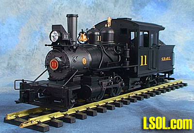 Here is an Outside/In look at the locomotive. TABULATED DATA: Length: Twenty inches (coupler face to coupler face as delivered) Eighteen inches (footboard to footboard) Width: Four and three-eighths inches (measured at cylinders) Height: Six and five-eighths inches (measured to top of spark arrester) Weight: Seven pounds, Two ounces Wheels Back to Back: Front truck 1.571 inches Drivers 1.579 and 1.569 inches Trailing truck 1.565 and 1.569 inches G1MRA standard is 1.575 inches Electrical: Starting voltage: 3.76 volts forward, 3.84 volts reverse Full slip: 1 amp at 6.70 volts Stall: 2 amps at 8.05 volts PACKAGING: 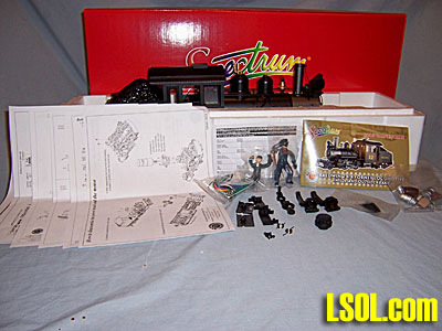 The locomotive comes packed in a clam shell foam container. The locomotive arrived with no damage or loose parts. Paint was in excellent condition.
Packed with the locomotive are five pages of illustrated documentation along with a registration card. An owners manual is included but there is no DVD. The lack of the DVD was a surprise since they contain a history of the locomotive plus detailed maintenance instructions. All of this information is included in the Owner's Manual. It sure would have been nice to receive a DVD with the Forney. 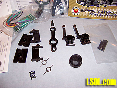 These are the extra couplers, coupler shank, and coupler boxes. The documentation illustrates installation of the couplers and coupler boxes. You will also receive a pre-wired DCC plug for adding an after-market decoder, the standard engineer and fireman figures, a package of the always popular detail items, spark arrester, and re-railer. No smoke fluid was included. Note: Packed with the re-railer are two short black metal wires. These wires have slight bends on each end. These wires are the lubricator lines that go in the top of the cylinder valve chests. They are not shown on the exploded parts diagrams.
OUTSIDE/IN REVIEW: First up is an outside look at the engine's details. 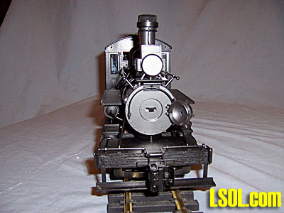 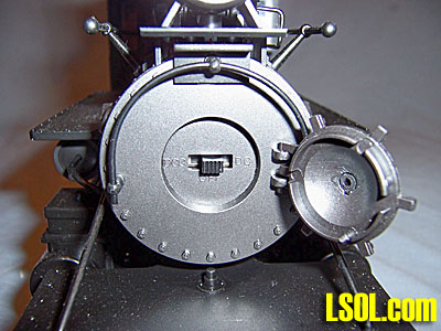 Here are two views of the locomotive's front. The switch for the smoke unit is located behind the door. Note that all detail on the front of the locomotive is metal. There is a cut bar but no chain to connect the cut bar to the coupler lift pin. The foot board is plastic with a good wood grain texture. The second picture shows the smoke unit switch. It has three positions. Left is DCC, center is Off, and right is DC.
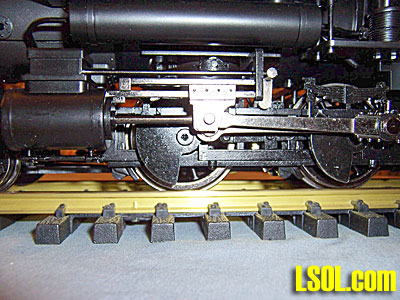  Illustrated here is the most glaring error on this locomotive. The center line of the steam cylinders are around a quarter of an inch higher than the center line of the driver axles. Now how could the designers and those that approved the design miss this major error? A locomotive's cylinder center line should be on the same plain as the center line of the driver axles. This major mistake really takes away from the "look" of the locomotive. Plus it's just not correct. While this misalignment will not affect operation of the locomotive it still is a major mistake. To drop the cylinders to align with the center line of the driver axles will take some major modifications. Most difficult will be dropping the Stephenson valve gear, since it is working gear.
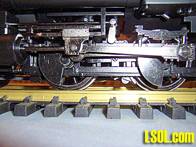
 Here is the driver's springs and spring hanger detail. While the axles are mounted rigid in the locomotive the springs have equalizers and transverse equalizer. A nice detail even though the axles do not move. 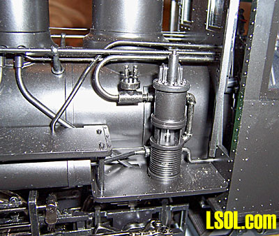 The locomotive has this well detailed single stage air compressor mounted on the left side. Also note that the front cab door is slightly open.
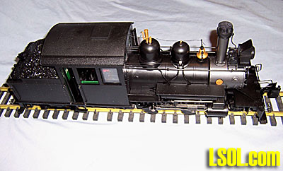
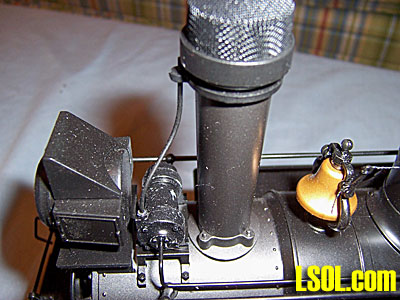 The generator is metal. Note the exhaust pipe that runs up the stack. Headlight is well detailed and contains a white LED. The stack spark arrester is removable. 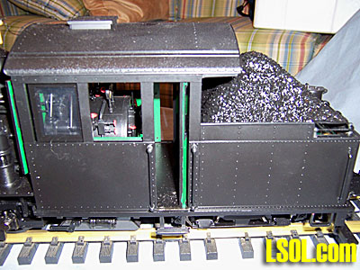 Left side with cab door open. The doors are not spring loaded so they will stay open. Nice all-weather cab with good rivet detail.
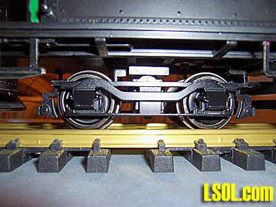 Rear truck side frame detail. Brakes are outside hung. This truck differs from that of the wood cab version. 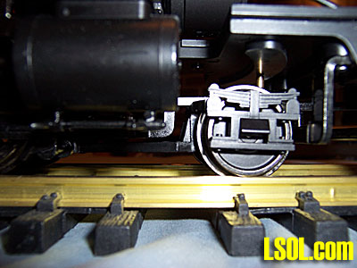 Front truck detail. Outside suspension with good spring detail. The truck moves freely from side to side. There is a spring loaded plunger to help keep the truck in contact with the rail. There is enough up and down movement so that the truck should not derail on even less than smooth rail.
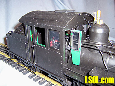 Right side of cab with front cab door open. The front cab doors are spring loaded. They will not stay fully open due to the springs. To keep these doors fully open some type of door stop will have to be employed. Whistle and pop valves are brass. 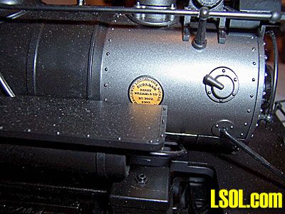 Baldwin builders plate. Crisp lettering. In the center is printed Burnham Parry Williams & Co. No. 3972, 1909.
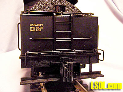 Tender, rear view. Metal cut lever, railings, and grab irons. Footboard is plastic with heavy wood grain. 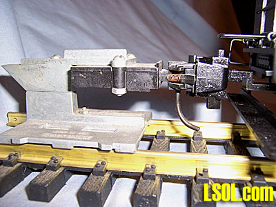 Coupler height matches the Kadee height gauge. Should be no problem coupling with Bachmann 1:20.3 rolling stock or that of manufacturer's that use the standard Kadee height.
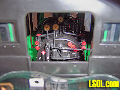 View looking into cab from the rear. Note globe valves, water level sight glass, throttle, backhead tray with two oil cans. and tri-cocks. The cab interior is well detailed even though much of the detail is difficult to see due to the all weather cab. 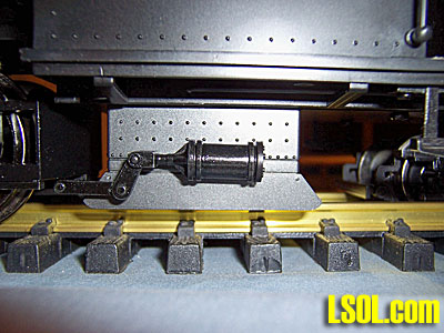 There is a brake cylinder mounted on each side of the locomotive. There is no air line going to either of the cylinders. Brake cylinder rigging is not complete. Not mentioned previously, there are air tanks under each running board with air lines.
 Overall view of the locomotive from the top. The roof hatch opens and has a roof hatch brace to keep the hatch open at different heights. 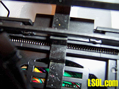 This is a view of the underside and the rear coupler shank coil centering springs. As delivered the rear coupler can move a full arch from side to side. This is the same arrangement used on the 2-6-6-2T. In service this setup has worked well on the 2-6-6-2T so it should work equally as well on the Forney. Note a portion of the speaker grill can be seen. The grill opening will take a 3 inch speaker. The speaker will have to be low profile to fit under the socket mounted in the tender.
 In this picture the rear truck has been moved to one side. In addition to the rear truck pivoting on its king post the rear truck can be left in its unlocked mode so it will slide side to side. This arrangement should work when running on three foot radius curves. 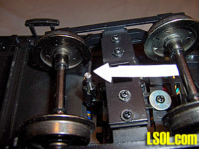 The arrow is pointing to the rear truck locking pin. With the pin engaged the truck will not slide side to side. The truck pivots on its king post. This is the mode that most operator's will use except when running on the tightest of curves.
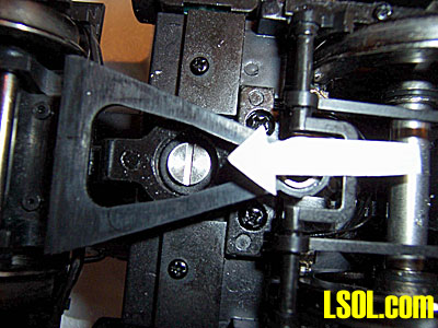 The large silver slotted head screw is used to secure the motor block so it will not pivot under the locomotive. In order for the motor block to pivot this locking screw is removed and stored in a threaded hole at the back of the motor block. As shipped the motor block is secured by this large screw and will not pivot. With the screw removed the motor block will pivot in much the same manner that the engine under a Forney would pivot. With the motor block free to pivot along with the rear truck unlocked the Forney should have no problem negotiating three foot radius curves or three foot radius turnouts. 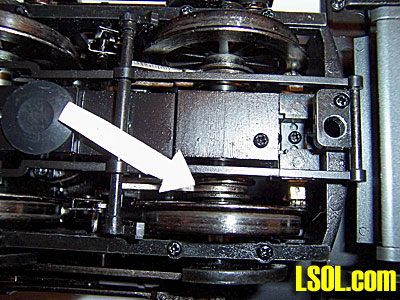 This is a view of an eccentric for the Stephenson valve gear. The eccentrics are mounted on the rear driver axle. The eccentrics give motion to the valve gear and valve rod that enters the steam chest. Several items of note. The firebox flicker is bright using LEDs as on previous models. Fire box draft doors, front and rear, open so that you can see this flicker. There is a low intensity cab light that gives a nice glow to the cab interior. Electrical pickup is through small rollers that run against the inside of the outer edge of the drivers. The rear truck also has electrical pickups, using the same system that first appeared on the 1:20.3 caboose. This truck pickup system is very free rolling and exhibits good electrical pickup on even some less than clean track.
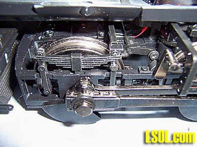
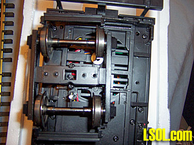
Now for an Inside look: 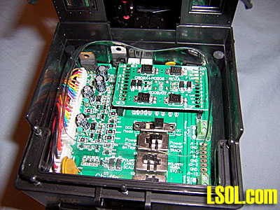 The main socket is located inside the tender. Access is gained by lifting the coal load. The coal load just sets in place held there by the edges of the tender shell, so it's easy to remove. This is the same type socket used on the K-27 and the 2-6-6-2T. I plan to install an RCS PnP receiver in the socket and run battery power. In this picture there is a dummy DCC socket in place. This dummy socket stays in place when the locomotive is to be run on track power. There are four switches on the main socket. They are; (1) Motor On or Off, (2) Polarity NMRA or Large Scale, (3) Pick Up Track or Battery, and (4) switch for DCC or DC. Note there is a clear plastic trough around the edge of the tender shell. It would seem this is to keep water from entering the tender and shorting the socket. What I didn't find is any type of drain to carry water from this trough to the outside. 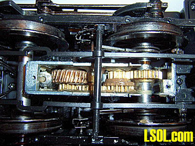 Here the gear case cover has been removed. In order to remove the gear case cover the brake rigging must be taken loose. The case cover is metal and held in place by two screws. There is a rubber lubrication port plug in the case cover. Gears may be lubricated by removing the plug and adding grease to the gear train. The gears appear to be phosphor-bronze a similar material that was used in the K-27 and 2-6-6- 2T. Gears are driven by a worm gear at the front of the gear case.
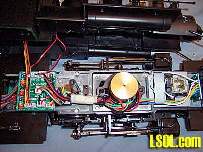 The boiler, cab and tender have been removed for this picture. The boiler, cab and bunker are held in place with eleven screws. There are two screws under the headlight, one screw down inside the steam dome, and eight screws under the rear chassis. Removal of the boiler, cab, and bunker is illustrated on sheet G809X-IS004 of the supplied documentation. The smoke unit is to the right of the picture. Under the smoke unit are six metal plates bolted to the chassis. These plates give extra weight to the locomotive. The large gold colored round object is the flywheel. Under the flywheel, mounted on the motor leads is a noise suppression PCB. To the left is the engine PCB. Wires from this PCB go to the main socket in the tender. The motor appears to be the same size as that used in the 2-6-6-2T. There is no external marking on the motor that I could find to identify the manufacturer. It is probably a Mabuchi that uses metal for the brush end, unlike the plastic found on most other motors used by Bachmann. This completes the Outside/In look at the Forney.
CONCLUSIONS: ON THE PLUS SIDE: This is a highly detailed, for the most part, well executed addition to the Bachmann fleet of 1:20.3 locomotives. Access to the socket in the tender is easy and straight forward. All components, be it the air compressor, generator, headlight, etc., are well done. The castings are crisp with no flaws. Paint is excellent. The builders plate is well done. I found no loose or missing screws. Wiring and solder joints all appeared to be well done. There should be no problem with the wiring if all the models are assembled as the one reviewed. All wheels run true with no wobble and are concentric on their axles. Driver counter weights are tight on the axles and mounting screws were tight. Cab and backhead detail is excellent. There are globe valves all over the place. On balance this is a very nice model of the Forney. I would purchase another and just look the other way when it comes to the mounting of the cylinders.
A FEW ISSUES: First would have to be the major mistake with the mounting of the steam cylinders in relation to the drivers. As mentioned previously you have to wonder what the designers and those that approved the design were thinking when the Forney was cleared for production. It's a real shame that such a well detailed locomotive should have this major, glaring error. The lack of a DVD, while no big matter was none the less a disappointment. While additional couplers are provided, the documentation is not complete in illustrating or addressing the installation of the body mounted coupler pockets and their components. Plus, no mention is made of what has to be accomplished to mount the offset shank couplers in order to match up with rolling stock that uses truck mounted couplers. The offset couplers to lower coupler height are mounted on the coupler shanks intended for the body mount couplers. To lower coupler height on the factory installed couplers these couplers will have to be exchanged. To lower coupler height removed the offset couplers from the supplied coupler shanks and use them to replace the couplers that are factory installed on the Forney. A single screw attaches a coupler to its shank so the change is a simple matter. Once this exchange is made the couplers on the Forney will align with truck mounted couplers. 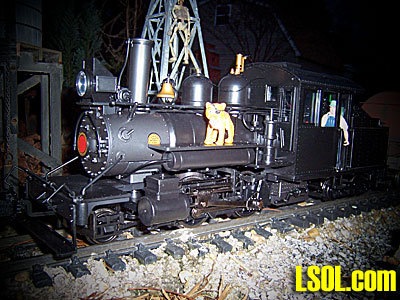
| Coal Load |
| Hey TinkerAnother fine detailed article on the Forney. The only thing I did not care for is the coal load being so high.Looking at the photo to me it just seem out of place.Gator |
| Bob Gentile - 01/13/2010 - 03:36 |
| Details |
| While I have never been a Forney fan, this model looks to be very well detailed. |
| Rick Henderson - 01/13/2010 - 05:56 |
| Great job |
| Hay, Jon: You did a great job with all the pictures you took. You could see the detal that you where explaing very clear. Looking at the picture of the gear box with all it's metel parts show's the engine should have a long life and some storng pulling power. Hay Gator!!! Nice seeing your name. It's been awhile since we said Hi. Hope all is safe and well with you and yours. Cap |
| John F. Schwartz (CAPPER) - 01/13/2010 - 10:10 |
| Forney |
| I am a fan of the smaller locomotives like the Forney, and JD I really appreciate the time and effort you took to show us this nice little locomotive. I am just wondering if the cylinders can be lowered while leaving the steam valves in place. Its interesting that Bachmann would make a working Stephenson valve gear and maybe its clearance issues with doing that that cased them to mount the cylinders too high. Either way the cylinder height is a shame. Looks like a nice little locomotive and thanks again JD for showing us the details of this locomotive. |
| David A. Maynard - 01/13/2010 - 14:15 |
| Forney |
| Jon, congratulations on the review, nice job. Good spotting with the cylinder alignment. Regarding the SR&RL use of Forneys, they had eleven 0-4-4 and three 2-4-4 versions. No.8 (inside frame) was ex Sandy river No.16 built in 1907. No.9 (frame, unsure but most likely outside) was purchase new and built in 1909 and No.10 (outside frame)also new and built in 1916. I noticed the Bachmann units carry the numbers 11 & 12, for those interested, SR&RL had no locomotives of any type carrying those numbers. |
| Brian Carter - 01/13/2010 - 16:47 |
| Coal Load |
| JD: Great review. Coal load may need to be enhanced with a set of coal boards. Will have to consider this beast if the price gets just right. Not sure what my other 7 LGB Forney's will think of it. |
| Jim O'Connor - 01/13/2010 - 17:13 |
| Question and suggestion |
| Is the pickup from the drivers for track power, and if so, is this transmitted via the valve gear as with their 0-4-0 tank engines, and not from a wiper pickup on the front driver. (and) for a better pickup, and perhaps improving on keeping oxidation down on the drivers, why could they not have engineered a pickup on the back support truck, giving an eight point contact area ?. Otherwise a really beautiful reproduction of a favourite wheel arrangement. Great review, Jon. |
| Kirke Fay - 01/17/2010 - 08:09 |
| Electrical Pickup |
| Kirke, I guess I didn't make it clear in the review. Check the last paragraph on page 14. There it's mentioned that electrical pickup is through small rollers that run against the back of each driver. The paragraph goes on to state that the rear truck has electrical pickup. Guess I should have stated that there are eight electrical pickup points on the Forney. The electrical pickups on the rear truck are some of the most positive I've seen. A very innovative piece of engineering. As a side note. Bachmann 0-4-0 locomotives, all versions, have electrical pickup on the backside of each driver. In no case is any electrical pickup transmitted through the valve gear. |
| JD Miller - 01/17/2010 - 09:09 |
| 0-4-0 Kirke Is Correct |
| Kirke, I STAND CORRECTED. Power DOES flow through the side rods, etc. on the 0-4-0 locomotives. Power is picked up by the drivers and it is "shared" between the drivers by the side rods. The side rods, connecting rods and valve gear is all "live" on each side of the locomotive. All these years and I really never looked at the metal side rods, and other components as being live. Sorry for my mistake. I should pay more attention to what I'm looking at. |
| JD Miller - 01/17/2010 - 12:45 |
| Outside/In Article Correction |
| We have updated the article about counter weights. The inside frame version DOES HAVE DRIVER COUNTER WEIGHTS.Sorry for any confusion this mis information may have caused any Team LSOL members. |
| JD Miller - 01/18/2010 - 22:22 |
Top of Page
|


