Product Close-ups
Exclusive: Aristo Craft Train Engineer Revolution
Dec 17, 2008


By David Bodnar
LSOL.com Electronics Editor |
Author
Bio
For the last two years I have had the privilege of working with Lewis Polk and the staff at Aristo Craft as the Train Engineer Revolution went from a rough draft of an idea to a finished product. I would like to give you an exclusive and detailed look at the Train Engineer Revolution and show you, step-by-step, the process you will need to follow to get your first Revolution Locomotive running!
|
For the last two years I have had the privilege of working with Lewis Polk and the staff at Aristo Craft as the Train Engineer Revolution went from a rough draft of an idea to a finished product. I received one of the first sample units in late November and have been putting it through its paces as I worked on the instruction manual that will guide users as they set up and use this extraordinary device. 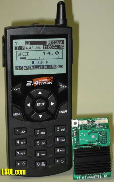 In this article I would like to give you a detailed look at the Train Engineer Revolution and show you, step-by-step, the process you will need to follow to get your first "Revolution Locomotive" running!
Features The highlights of the new Train Engineer clearly differentiate it from its predecessor and other remote control systems: - The 2.4 gigahertz radio system is bidirectional. That means that the transmitter not only sends commands to the locomotive but it also gets feedback from the receiver in the locomotive.
- Spread spectrum radio transmission provides immunity from interference caused by radio sources that are in the same frequency range.
- Outdoor range exceeds 400 feet.
- Locomotives are identified by name and road number such as PACIFIC 5305 or MIKADO 3185.
- Information about the locomotive that is being operated is clearly displayed on a back-lit, graphical LCD display.
- Each transmitter can hold information on as many as 50 different locomotives.
- Multiple transmitters can independently operate additional groups of 50 locomotives without interfering with one another.
- Power can come from on-board batteries or track power.
- The receiver can supply 5 amps of power while accommodating peak loads that can go to 8 amps.
- Most transmitter control operations can be done with one hand.
- Textual information is keyed into the transmitter using the same technique that is used on cell phones.
- Six auxiliary outputs on the receiver can be used to operate sounds, smoke units or lighting.
- Each locomotive can have individualized setting that include start speed, maximum speed and momentum.
From the beginning the new Train Engineer was designed to be easy to operate so that model railroaders would be able to concentrate more on running trains and less on the complexity of the control mechanism. To this end the display presents setup and control items in plain English. After initial setup and a brief introduction to the transmitter and receiver little time should need to be spent with the printed manual.
Transmitter Control Overview 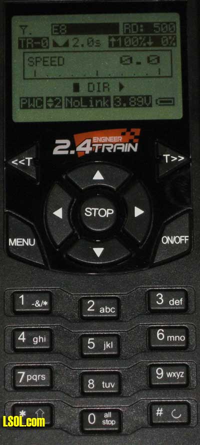 - Screen - The high resolution / backlit graphic screen is used to display information and to provide operation assistance.
- Power on/off - press "ON/OFF" to turn the unit on. Press and hold the "ON/OFF" button for 2 seconds to turn the unit off.
- <<T / T>> - Used to select the active locomotive. Press the <<T key to scroll left through the list of locomotive names and the T>> key to scroll right. The locomotive names and road numbers will be displayed at the top of the screen.
- Arrows - When operating a locomotive the up and down arrows increase or decrease speed and the left and right arrows select direction. When accessing menu items the up and down arrows scroll between items and the left and right arrows change that item's value.
- STOP/ENTER - When operating a locomotive the STOP/ENTER button stops the active locomotive and sets its speed to zero. When accessing menus STOP/ENTER is used to confirm a selection. (note that the labeling on the transmitter now shows only STOP on the key that will show STOP/ENTER in production units)
- Menu - From the Operating screen selects the unit's setup menu. When accessing menus pressing MENU will move you back one menu level like an Escape or Back key.
- Number / letter keys - When entering textual or numeric information the use of these keys is identical to the use of keys on a cell phone.
- Number keys 1-6 - When operating a locomotive, keys 1 through 6 are used to access six auxiliary functions that may have been programmed into your engine's controller. For example, pressing key "1" might activate the sound card's whistle and "2" its bell sound while "3" might turn the smoke unit on or off.
- Number key # - When the Operating screen is being displayed pressing the # key accesses the Quick Menu List.
- Number key 0 / all stop - When the Operating screen is being displayed pressing the 0 key for 2 seconds will stop all locomotives and set their speed to zero. To restart locomotives press the <<T or T>> keys to select a locomotive and press the up arrow.
Receiver Installation If you are using one of the newer Aristo Craft locomotives that has a "Plug & Play" port, installation of the receiver should only take a few minutes. Installation in other locomotives takes a bit more time but is no more difficult than the installation of other locomotive controllers. I installed the receiver in a new Aristo Craft E8 in less than 15 minutes. Here is what is involved. First remove the body from the locomotive's frame. The screws that need to be removed are clearly marked with arrows. Separate the body shell from the frame, laying the top of the locomotive on a towel or other padded surface. The top of this photo shows the body of locomotive which contains two smoke units, a high quality speaker and the electronic circuit board. The frame is at the bottom. .jpg) Here is a close-up photo of the electronic control circuit board as it comes from the factory. Note that there is an open 10 pin connector on the right. There is a similar 12 pin connector on the left that has a factory installed plug in it. The plug can be identified by the small triangle at one end. .jpg) In this photo of the Revolution receiver you can see the two headers, one 10 pin and one 12 pin, that will plug into the locomotive's circuit board. 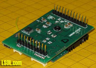 To install the receiver just pull out the plug that is factory installed in the 12 pin connector. Next plug the Revolution receiver's headers into both the 12 and 10 pin connectors being careful that the pins are properly aligned and fully inserted into the locomotive's control board. If you have difficulty getting the board into place because of the three wires that go to the plug labeled "REG" you can pull the cable out, insert the board and put the cable back in place. 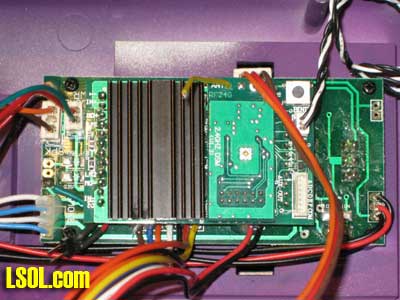 The last step in the installation is to install the "Bind" switch in a location where it can be reached once the locomotive is reassembled. The "Bind" switch is used to link the receiver and transmitter. Because the locomotive that is being used here has doors that open on the sides and rear I opted to glue the switch just inside one of the doors so that it would be hidden but could be accessed when needed. You could also mount it to the bottom of the locomotive by drilling a hole in the base or in the compartment on top of the locomotive where the smoke, light and motor switches are located. 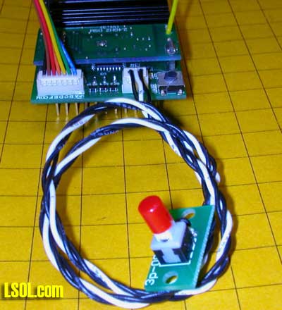 Here you see the "Bind" switch attached behind the rear door with hot melt glue. The other end of the switch cable goes to the socket on the receiver labeled "BIND". .jpg) It is easy to depress the switch by reaching through the rear door. 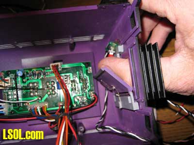 In this locomotive it is not even necessary to install the bind switch if you have long fingers. As you can see in this photo of the completed installation there is another bind switch (circled in yellow) on the receiver circuit board that you may just be able to reach by extending your finger through the rear door! 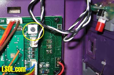 If you are not installing a sound board or the smoke unit control board just put the locomotive back together and your installation is complete!
Locomotive Configuration Each locomotive must be set up and introduced to the transmitter before it can be operated. Although there are a number of configuration setting that can be made only a few are necessary to get your train running. Turn on the transmitter by pressing the ON/OFF button. The main control screen will be displayed and will look something like this. 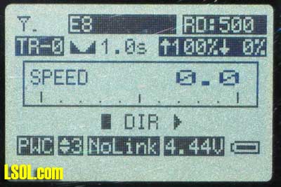 Press the MENU key once and you will see the main menu screen. 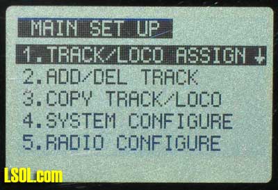 Press the STOP/ENTER key to select 1. TRACK/LOCO ASSIGN. Remember that the key on the transmitter that is currently labeled STOP will be relabeled STOP/ENTER in the near future. 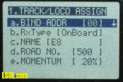 First you must select a bind address. The bind address is normally different for each locomotive and is a number from "00" to "49". (Note: if multiple locomotives are used to pull one train in a consist each locomotive will have the same bind address). Use the RIGHT ARROW or LEFT ARROW keys to select a bind address. For this installation let's just use the first address, 00. Press the DOWN ARROW to move to item c. NAME. Use the keypad to type letters or numbers to name the engine. Names may be up to 9 characters long. For example, GP40, EGGLINER or MIKADO. Text entry is done using the exact same method that is used on cell phones. A detailed explanation of this is included in the operation manual. Fortunately most of us already know how to do cell phone text entry and won't need to consult it! Once the name has been entered move down one more item to 4. ROAD NO. The road number can be up to 4 characters long and may contain letters and symbols. 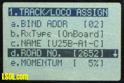
Even though the bind address, name and road number are all that are needed right now there are five optional settings that are worth mentioning: - e. MOMENTUM - sets the locomotive's momentum, the rate at which it accelerates. The higher the momentum value the slower the locomotive will speed up when you press the UP ARROW for acceleration.
- f. DELAY - sets the number of seconds that the locomotive will be completely stopped when its direction of travel is changed. For example, if delay is set to 3 seconds and you change the locomotive's direction it will decelerate to a stop and pause for 3 seconds before reversing and accelerating to the set speed.
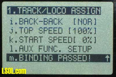
- j. TOP SPEED - sets the locomotives top speed as a percentage of its possible top speed. This comes in handy if you have visitors operating your trains who have a history of running them at too high a speed. Set TOP SPEED to 70% and that is all the faster the locomotive will go, 70% of its possible top speed.
- k. START SPEED - sets the speed at which acceleration of the locomotive begins. If you have a large locomotive or one that is pulling a long, heavy train you can set the start speed so that the power level will jump to the set percentage as soon as you begin accelerating. For example, if you have a locomotive that doesn't start moving till the throttle setting is at 25% you can set the start speed to that number and not have to wait for the speed to get to 25% before the train moves. As soon as you press the UP ARROW the speed will jump to 25%.
- l. AUX FUNCTION SETUP - sets the function keys to be either latching or momentary. To operate a smoke unit set the function key to latching so that the smoke unit goes on and stays on when you press the function key. Set a horn control function key to momentary so that the horn only sounds once when you press the key.
Binding the Locomotive and Transmitter The final step is to bind the transmitter and the receiver that was installed in the locomotive. This process establishes the link between the two and associates the settings we just made with a particular locomotive. To bind them follow these steps: - If you are running on batteries make sure the locomotive's battery is fully charged.
- If your locomotive uses track power turn on the power to the track. The voltage should be set to its maximum, but no more than 24 volts.
- Press and hold the BIND button on the locomotive that was just configured.
- Release the BIND button when the red LED on the receiver board and the locomotive's lights begin flashing.
- While the lights are flashing select menu item m. BINDING and press the STOP/ENTER button.
- In a moment the screen will show that the programming of the unit has been successful and the flashing will stop.
Operating the Locomotive Once binding is completed press the MENU key twice to return to the main operating screen. Confirm that the locomotive name and number that we just configured is displayed. Use the UP ARROW and DOWN ARROW keys to increase and decrease the locomotive's speed. The RIGHT ARROW and LEFT ARROW keys change the locomotive's direction. Control Screen Overview At this point a quick overview of the main control screen is in order. .jpg) - The antenna symbol in the upper left shows the strength of the radio signal between the transmitter and the locomotive's receiver.
- The next two items on the top line are the active locomotive's name and road number.
- The first item in line two is the number of the active locomotive. Note that this number shows the locomotive's position in the transmitter's memory and may change for a particular locomotive if locomotives are added or deleted. The first locomotive is shown as TR-0, not TR-1.
- The next number is the number of seconds that the train will stay stopped when its direction is changed.
- The next two numbers are the locomotive's maximum speed and start speed. Both are expressed as a percentage of the maximum possible speed.
- The box in the center of the display shows the locomotive's current speed. At the bottom of this box the speed of the locomotive is shown graphically.
- The next line shows the direction of travel for the active locomotive. When the arrow symbols point to the right the locomotive is going forward.
- The first item on the bottom line shows that the system is using PWC (Pulse Width Coding) speed control.
- The second item on the bottom line is the speed mode. This is a sensitivity level for speed of reaction after pressing the buttons that increase or decrease the locomotive's speed. For switching you might want a lower sensitivity and for big trains a faster key reaction. This item can be modified by accessing the Quick Menu List, which is described later in this article.
- LinkOK or NOLink tells whether the transmitter and receiver of the active locomotive are communicating.
- The next item is the voltage level of the transmitter's batteries. Fresh alkaline batteries should show about 4.5 volts. The last item is a graphic of the transmitter's battery level.
Adding a Second Engine To introduce another engine to the controller follow these steps: - Press the MENU key to return to the main menu
- Select 1. TRACK/LOCO ASSIGN
- Select a bind address as we did before. This bind address should be different than the one we used with the first engine.
- Enter a name and road number for the engine.
- Change any other settings that you want.
- Turn on the power to the new locomotive and press its bind button.
- While the lights are flashing select menu item m. BINDING and press the STOP/ENTER button.
- Wait for the programming confirmation message.
- Press the MENU key once to return to the main menu.
- Select 2.ADD/DEL TRACK.
- Use the UP ARROW and DOWN ARROW keys to select the locomotive that we just identified.
- Use the LEFT ARROW and RIGHT ARROW keys to select ADD and press STOP/ENTER. This will add the second locomotive to the list of active locomotives that will be displayed when you press the <<T and T>> keys from the main control screen.
Controlling More than One Engine at a Time Make sure that both engines have been identified in the transmitter and that binding has been successful. Place both engines on the same track, with one of them some distance ahead of the other. Use the <<T and T>> keys until the display shows the name and road number for the engine that is in front. Use the UP ARROW key to start it running slowly in a forward direction. Select the other engine with the <<T and T>> keys. Use the UP ARROW and DOWN ARROW keys to get it running at the same speed and in the same direction. Note that the displayed speed for both engines may not be the same when they are actually running at the same speed as it can vary from locomotive to locomotive. Multiple Locomotive Consists Multiple locomotives pulling the same train can easily be accommodated. To set up a consist of two locomotives follow these steps: - Configure one locomotive using the procedure outlined above.
- Bind the first locomotive and the transmitter
- Configure the second locomotive using the same bind address as the fist one.
- If the second locomotive will be running backwards change the BACK-BACK setting from NOR (normal) to REV (reverse).
- Bind the second locomotive and the transmitter.
- Press the MENU key once to return to the main menu.
- Select 2.ADD/DEL TRACK .
- Use the UP ARROW and DOWN ARROW keys to select the locomotive that we just identified.
- Use the LEFT ARROW and RIGHT ARROW keys to select ADD and press STOP/ENTER.
- Press MENU to return to the main control screen.
- Place both locomotives on the track a few feet apart.
- Select the locomotive with the <<T and T>> keys.
- Speed up the locomotives and confirm that both are going in the same direction.
- Couple the locomotives and you are ready to go!
Note that the transmitter treats the locomotives in the consist as one locomotive. You cannot give them different names or road numbers. Other Menu Options - 2.ADD/DEL TRACK The Train Engineer Revolution transmitter can store information on as many as 50 locomotives. Since it is unlikely that we would have this number of locomotives active at one time we can use this menu item to limit the number of locomotives that show up when we press the <<T and T>> keys while viewing the control screen. Use the UP ARROW and DOWN ARROW to display locomotive names and the RIGHT ARROW and LEFT ARROW to add or delete a locomotive from the active list. Press STOP/ENTER to confirm adding or deleting.
Other Menu Options - 3.COPY TRACK LOCO Once you set up a locomotive with a set of options you can copy that locomotive's characteristics to another locomotive based on its bind address. For example, if you have set up bind address 00 and want to copy it to bind address 01 just select 00 as the FROM: and 01 as the TO: and move to COPY and press STOP/ENTER. All of the data information from the first locomotive will be copied to the second. Other Menu Options - 4.SYSTEM CONFIGURE a. POWER OFF - sets the number of minutes that the transmitter will stay on if no buttons are pressed. This can range from 1 to 30 minutes. Note that the trains will continue to run even if the transmitter shuts itself off and that the transmitter remembers all of its settings when it is turned back on again. b. BRIGHTNESS - sets the backlight brightness. Lower brightness levels prolong battery life. c. CONTRAST - adjusts the LCD contrast level. d. KEY SOUND - selects if the beep that is heard whenever a key is pressed is on or off Other Menu Options - 5.RADIO CONFIGURE a. RF-CHANNEL (12-26) - this can be changed if you suspect that interference from a local source is effecting the range of the system. b. GROUP ID (0-9999) - If you have more than 50 locomotives that you want to control or you have multiple areas that you want to control with separate transmitters, you can select a different Group ID for each transmitter and they will operate independently of one-another. It is also important that visitors who might bring their own Train Engineer Revolution and locomotives have a different group ID. Other Menu Options - 6.QUICK RF BINDING This item is the same as the BIND option in the TRACK/LOCO ASSIGN menu. Other Menu Options - 7.MY MEMO Allows you to enter your name and other identification information into the transmitter. Other Menu Options - 8.RESET MEMORY This option resets the transmitter's memory to its factory settings.
Quick Menu List Options This supplementary menu is accessed by pressing the "#" key while viewing the main control screen. AUX FUNCTIONS - shows the auxiliary output setting for the currently selected locomotive. The current state is shown (on or off) and its setting, momentary or latching. STEP SPEED - this item can be set to a value from 1 to 5. When set to a lower number the rate at which the speed increases when you hold the UP ARROW will be at its slowest. A higher number will cause this rate to increase. When set to its highest value the speed can change from 0 to 100% very rapidly. A-Z NAME SEARCH - displays an alphabetized list of the locomotives that have been entered into the transmitter. This provides a quick way to find a locomotive in a long list. ABOUT SYSTEM - shows the version of the internal software While we are on the topic of version numbers, Aristo Craft plans on doing transmitter version updates for a cost of $18.00 which includes return postage and handling. The reprogramming of the transmitter will not overwrite all of the data you may have entered, just the underlying software.
Special Features The Train Engineer Revolution can control more than just your locomotive's motor and lights. There is a small circuit board that is included with the package that can be used to turn smoke units on and off. There are also six auxiliary outputs on the receiver that can be used to control sounds and other devices that you may have installed on your locomotive. Smoke Unit Control Board Installation The Revolution receiver cannot operate the locomotive's two smoke units directly. Because of the current draw of the smoke units a small controller board must be installed between the receiver and the smoke units. This photograph of the smoke control board shows the signal wires, which are connected to the Revolution receiver, and the two smoke unit wires, labeled SMOKE-1 and SMOKE-2, that connect directly to the smoke units. Note that the control board can accommodate one or two smoke units. Only use this control board with smoke units like the ones shown in the photographs. .jpg)
The steps below show how to install the board with two smoke units. The procedure for a locomotive with only one smoke unit is the same, you just don't use the second smoke connector, SMOKE-2. - Unplug the power cables from the smoke units.
- Plug the cable that you just removed from either of the smoke units into the small socket on the smoke control board.
- Plug the smoke plugs, labeled SMOKE-1 and SMOKE-2, from the control board into the smoke units.
- Connect the black signal wire to the black wire, the common terminal, from the receiver's auxiliary plug,
- Connect the white signal wire to one of the six colored wires that are on the receiver's auxiliary plug.
note: The Auxiliary plug has contacts that are labeled "a", "b", "c", "d", "e", "f" and "com". Button 1 on the transmitter controls contact "a", button 2 controls "b" and so on through button 6 controlling "f". The wire that you use to control the smoke unit is arbitrary. I selected "f", the brown wire, and reserved "a" and "b", the blue and green wires, for the horn and the bell on the sound card.
- Set the switch on the top of the locomotive that normally turns the smoke units on or off to "on".
Here you see both smoke units connected to the smoke controller which is mounted to the side of the locomotive's body in the upper right corner. .jpg) Now you can turn the smoke units on or off just by pressing one of the six number keys on the transmitter. Make sure you set the selected function button to LATCHING rather than MOMENTARY so that the smoke unit stays on when you press its function key.
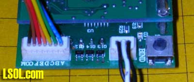
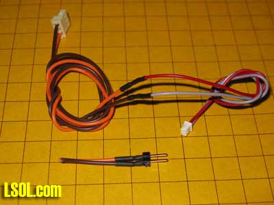
Sound Board Installation Installation of the Dallee diesel sound card that was chosen for this locomotive is not "Plug & Play" but can be accomplished by following the instructions below. Four connections are made between the Dallee diesel sound card and the locomotive's main circuit board and three connections are made to the Train Engineer's receiver board. This table shows the connections that need to be made.
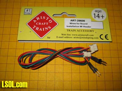
| Dallee Sound Card | Main E8 Board | 7 pin AUX plug on TE receiver | | J3 Black | SOUND PWR - red wire | | | J3 White | SOUND PWR -green wire | | | J3 Red - Not Connected | | | | J1 Red - Not Connected | | | | J1 Grey | SOUND PWR - red wire | | | J2 Red - Not Connected | | | | J2 Grey | | Black COM | | J4 Red | | Green "a" - bell | | J4 Grey | | Blue "b" - horn | | SPKR | SPK | | 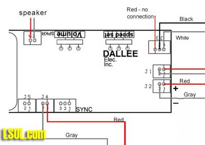 - Obtain a set of sound card installation cables from Aristo Craft. This is part # 29608
 - Cut the end with two metal pins off of the orange and black cable leaving the three pin plug on the other end.
- Strip the insulation off of the orange and black wires and solder them to the stripped ends of one of the two pin red and grey connecting wires that came with the Dallee sound card. Insulate this connection with tape or heat shrink tubing.
.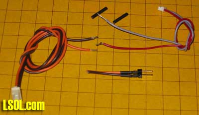 - Here is the completed cable assembly that will connect the sound card and the locomotive's speaker.
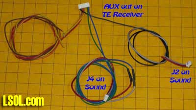
 - Two more cables need to be made. The first connects the 7 pin auxiliary plug that fits into the receiver's AUX socket and two of the plugs that go into the Dallee sound board, J2 and J4. Note that the red wire on J2 has been cut as it is not used. At this time we are only using three of the control wires from the AUX plug, the black, common wire and the blue and green wires that are activated by buttons 1 and 2 on the transmitter. These will operate the horn and bell sounds.
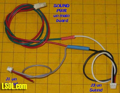
 - The other plug is shown here. It connects the green / red plug that goes into the SOUND PWR plug on the locomotive to the plugs that go into J1 and J3 on the Dallee card. Note that the red wires on J1 and J3 have been cut as they are not used.
- The larger plug on the black and orange cable assembly plugs into the plug on the locomotive's control board labeled "SPK", for speaker. The other end of the cable plugs into the jack on the Dallee card marked "SPKR"
Mounting the Sound Card Dallee suggests that the sound card be mounted on the cover that goes over the top mounted switches on the locomotive. Although it would fit there I didn't like the idea of drilling holes and routing wires through the top of the locomotive to the sound card. Once again the opening doors provided the answer. I glued a triangular block of wood to the inside of the locomotive body beside one of the doors. .jpg) The angle of the wood allows access to the volume adjustment potentiometer with a screwdriver that goes through the door. .jpg) Before mounting the sound card I took one precaution. The potentiometers on the board are only supported by the three wires that connect them to the board. Pushing on these pots from the side bends them over and eventually they would break off. Here you can see the pots and the wires that support them. Also note that the black wheel that rotates to change settings extends through the pot and out the back. 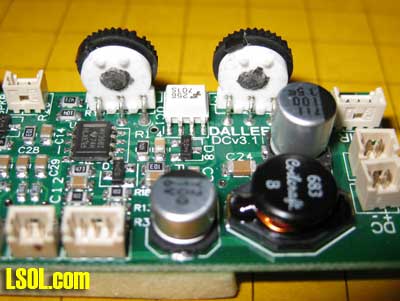 A support made of hot melt glue was added to the back of the pots to support them. Make sure you put a drop of grease on the back of the pot where the wheel comes through so that the glue will not adhere to the rotating part of the pot and keep it from moving. Now we can safely push on the controls through the door! 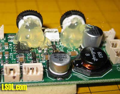
That completes the installation of the accessories. Our E8 is now set up so that button 1 on the keypad turns the bell on or off, button 2 sounds the whistle and button 6 turns the smoke units on or off. Conclusion There are a number of other features and options that I have not covered in this article but you can rest assured that each and every one will be explained in great detail in the manual. I am sure that that there will be changes to some screens and procedures as the system is refined and becomes even more capable. I hope that have an opportunity to try out the Aristo Craft Train Engineer Revolution yourself. I am very impressed with the construction and design of the unit. During the time that I have spent working with the transmitter and receivers I am pleased to say that I have had zero glitches or unexpected actions. In spite of its being brand new it operates as a mature, stable product. I am sure you will find, as I have, that it is truly revolutionary and that it will be a worthwhile addition to any garden railroad. |

