Product Close-ups
Bachmann Heisler: A Mechanical Perspective
Jan 28, 2004


By Jon D. Miller
LSOL.com Reviews Editor |
Author
Bio
Bachmann's latest addition to its line of 1:20.3 Spectrum locomotives is a fitting capstone to the series of geared locomotives.
|
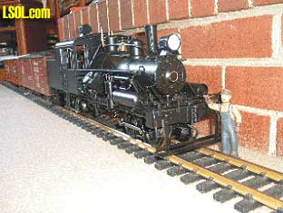 Bachmann's latest addition to its line of 1:20.3 Spectrum locomotives is a fitting capstone to the series of geared locomotives. Starting with the Shay, each follow-on geared locomotive has raised the bar for detail, fidelity, and engineering innovation. Large Scale operators interested in owning and operating geared locomotives now have a selection of the highest detailed yet affordable locomotives on the market. It just doesn't get much better than this. Close on the heels of Dave Maynard's excellent "First Look: Bachmann Heisler" article I have attempted to go below the surface to explore some of the locomotive's inner workings. I recommend that Team LSOL Members read Dave's article and view his pictures that provide a true flavor of this most highly detailed engine. A read of Dave's article, if you haven't done so already, will help set the stage for what is to follow. With each addition to the Bachmann geared locomotive stable I'm impressed with their engineer's innovation and attention to detail. The Heisler comes to the Large Scale scene with yet another completely redesigned motor block and drive system. Unlike previous geared engines the Heisler features a die-cast metal case and cover. The motor blocks in the new Heisler build on and refine previous examples used in the Shay and Climax. Let's start with an overview of this totally redesigned motor block, the heart of the Heisler. 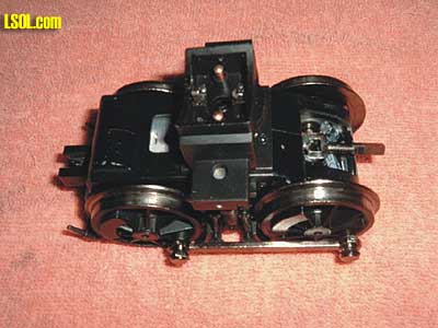
Front Motor Block 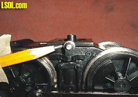 Notice Addition of Roller Side Bearings
The motor blocks are easy to remove. Motors are attached to bolsters that mount with screws placed through the side frame. Removing these screws allows the motor blocks to drop out. The exploded diagrams supplied with the engine identify the location of these mounting screws.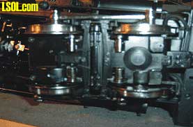
View of Bottom Motor Block Cover The bottom metal covers are held in place with four fine thread screws In the bottom view picture note the round silver cylinders behind the edge of each driver. These are the electrical contacts. Bachmann has changed from the encapsulated small metal balls that were used to make contact on Shay and Climax models. The pickups are now small metal rollers . These rollers should further reduce drag on the drivers while enhancing electrical pickup. Also note the now familiar rubber plug in the center right side of the cover. This plug can be removed for lubrication purposes. Unlike previous Bachmann models, pre-operation lubrication of the drive gears and shafts is not a stated requirement. On the Heisler I received there was sufficient lubrication in both motor blocks. Now let's take a look inside one of the motor blocks, noting that both motor blocks are identical. 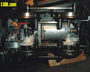 Motor Block Internal View The round cylinders that hold the roller electrical pickups are also evident in the above picture. Motors are double worm drive of the same type used in other Bachmann engines. The beveled gear on the left side of the picture provides motion to the drive shaft and universal joint that exits the end of the motor case. There is a printed circuit board (PCB) along each side of the case. These PCBs pick up power from the wheel contacts and send the power to a main PCB mounted in the tender. Power is then returned to the motor, first passing through a noise suppression PCB on its route to the motor leads. Wires, capacitors, etc., are evident at the extreme left side of the picture.
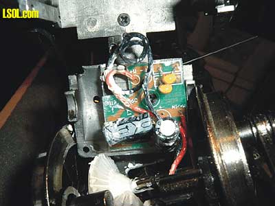 Motor Noise PCBSuppressor The motor noise PCB is attached to the motor case bottom cover. With the suppressor in place it's a tight fit inside the case. Care must be exercised when putting the cover back in place so that the wires do not become entangled in the gear train. On the down side, these Bachmann motor noise suppressors have been noted to overheat a motor. In some instances the heat buildup is so great that the plastic end of the motor that holds the brushes will melt. I removed these suppressors and replaced them with ceramic capacitors soldered directly to the motor leads. Electronic noise suppression is especially critical when operating with battery radio control. The same may be the case with DCC, however I have no experience with DCC so cannot comment on the issue. If you decide to remove the Bachmann noise suppressors retain them in the event the unit has to be returned to Bachmann under warranty. Removing the suppressors may void your warranty. If removed, re-install the suppressors before returning a unit to Bachmann for service. Motion to turn the cranks shaft and in turn the cylinder connecting rods and valve gear eccentrics is transmitted from both the front and rear motor case. 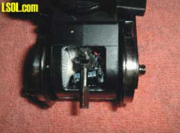
Top View of Motor Case Showing Universal Joint and Drive Shaft Collar The opening in the motor case to allow exit of the drive shaft has caused some concern among Large Scale operators. These folks think that having an open motor case will lead to the introduction of foreign matter that will damage the gear train. Only time will tell if this concern is with foundation. I've run Lionel LS engines with exposed drive gears for years without any adverse effect being caused by dirt, grit, etc. The opening in the Heisler's cases is up on the top end and is protected to a certain extent by the chassis of the locomotive. Note in the above picture, especially the area just above the opening, that the case is molded in two halves. The case consists of a left and right half with a bottom cover, as mentioned earlier in this article. 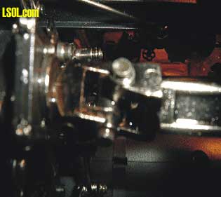 Metal Universal Joint The Heisler employs metal universal joints throughout the drive train. These universal joints are very similar in design to those used on the drive shafts of motor cars. Unlike the Shay and Climax, the all metal universal joints should prove to be more robust. In addition to the metal universal joints the Heisler uses square slip joints on the drive shafts. These slip joints are metal and similar in design to those used on previous geared locomotives. Lubrication of the universal joints and slip joints should be accomplished on a regular basis to avoid excessive wear and failure.
Drivers are attached to the axles by means of a center mounted screw. Drivers are not interchangeable between the inside frame and outside frame models of the Heisler. The inside frame Heisler's drivers have crank pins for attaching the side rods. On the outside frame versions the counterweights have crank pins with the drivers being plain. 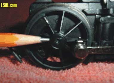 Center Mounting Hole For Phillips Head Screw Recommend that the driver screws be removed to add a small drop of Loctite 222. Using Loctite 222 will help insure drivers stay tight on the axles. When installing the mounting screws tighten them snugly but do not over tighten. Use caution so that the insulating washers and mounting collars are not misplaced. Refer to the exploded parts diagram for proper sequencing of the mounting collars and spacers. As previously mentioned the motor blocks are easy to remove from the locomotive. Power is passed between the motor blocks and the main PCB by spring loaded contacts. The following pictures show these contacts. 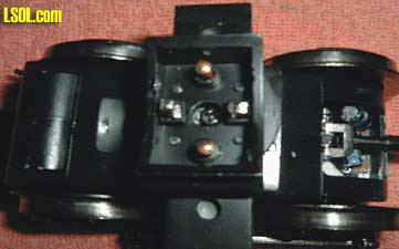 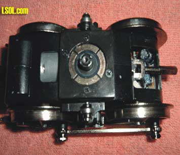 In the first photo the four electrical contacts can be seen inside the bolster's center box. These spring loaded contacts make contact with four brass strips mounted in the body of the locomotive. Note the large head Phillips screw that attaches the bolster to the king post of the power truck. Also the universal joint almost directly over the axle on the right side of the picture. Directly below the universal joint is the PCB mentioned earlier. The second photo shows the segmented contact ring mounted on top of the power truck. The king post is visible in the center of the ring. The spring loaded contacts mounted in the bolster make contact with these four segments. While not mentioned in the Bachmann instructions these contact rings should receive periodic lubrication. Just a small drop of light oil or Conducta may be added by tipping the engine on its side to apply the lubrication. Note also the side bearing roller on each side of the power truck.
Let's take a quick look inside the cab and the tender. The cab roof is held in place with four very tiny screws along the top edge of the front cab wall. Additionally there is one small screw on each side of the cab walls at the very back just below the roof line. Removing these screws allows the cab roof to be removed. After removing these screws very carefully lift the cab roof slightly, just enough to disengage the roof vent brace. Pulling up too far on the cab roof will break the brace. Once the brace is disengaged from its latching bracket the roof can be removed. 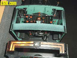 Cab Interior With Roof Removed The brass strips in the lower portion of the picture provide power to the cab interior light. The light is centered just under the cross brace that carries the brass power strips. The cab light is not real bright so that it does not distract ones attention. The brass strips also provide power to the reverse light mounted on top of the cab roof. 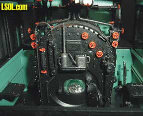 Back Head Detail The back head seems to be very complete. The Johnson bar is operational with a reach rod going to the valve gear. For all of its detail for some reason Bachmann neglected to install a throttle. That is twice now that the throttle has been left off one of their highly detailed Spectrum models. At the ECLSTS I'll have to ask H. Lee or the Bach-Man about this obvious oversight. Too bad this had to happen on such a highly detailed model. Either the throttle is missing or there is some other way to apply steam to the cylinders. The flickering fire box light works well on the model I have and is visible in all but the brightest sunlight. 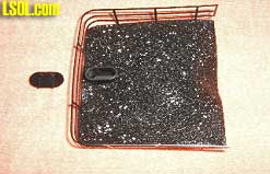
Coal Load Removed with Water Hatch Cover The coal load is easy to remove. The water hatch cover, to left in picture, is taken off to get at the Phillips head screw that attaches the load to the tender. Once the screw is removed the coal load is lifted directly up. It may take a little wiggling to get it free; just be careful not to damage the coal fence. With the coal load removed be mindful that the tender is no longer attached at the back to the chassis. Lifting up on the tender could cause the front anchors and screws to break. 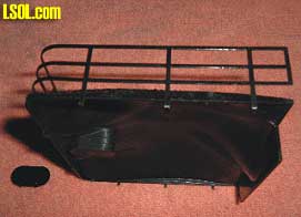
Coal Load Side View with Water Hatch at Lower Right
With the coal load removed we'll take a look inside the tender. The tender contains the main PCB and a large flat weight along with enough wires to wire up a small town! 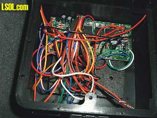 Another View Inside The Tender See, I mentioned there was enough wire to do a small town. The main PCB is mounted toward the front of the tender almost touching the back wall of the cab. Under the PCB is the tender weight. The weight covers the floor just about front to back and side to side. The hole seen in the lower part of the picture is where the coal load attaching screw goes through and into a metal stand-off that extends down to the floor of the tender. From what I've checked so far the color code of the wires match that of the color codes depicted on the exploded view wiring diagram. The wires trailing down to the lower right hand corner of the picture are those coming from the chuff contacts in the cylinders. By the way, the four wires referenced by Dave in his article are intended for use when installing a DCC decoder. The last several Bachmann locomotives have included these wires. The last place to look is under the locomotive. Here we'll take a look at the ash pan and crank shaft. 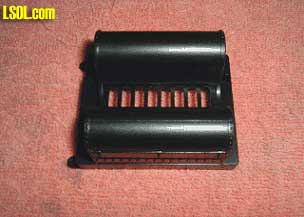
Ash Pan The ash pan is located directly under the fire box. That seems like a logical place for an ash pan. I've seen it referred to as a set of tanks and in fact from the side you get the impression it is a pair of tanks. The ash pan is held in place by three screws. Removing the ash pan reveals a large square hole in the chassis. This opening is where most folks have or will mount the speaker for a sound system. In checking with Phoenix Sound, John indicated they are supply a 2 1/4" speaker. This is going to be a tight fit. Those that have installed a sound system indicate it can be accomplished without too much difficulty. 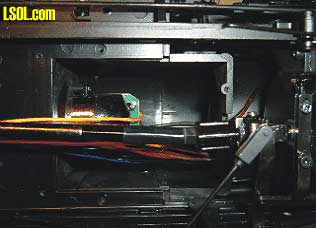
Looking Into the Locomotive Through the Ash Pan Hole Notice a large bundle of wires coming out of the hole that go to the tender and attach to the main PCB. There is room to move the wires aside in order to install a speaker. Partially blocking the view, toward the bottom of the ash pan hole in the picture is the drive shaft that extends to the rear truck. You can just make out one of the universal joints on the right under a brake rod clevis. The object down in the hole to the left with the green edge is the reflective housing for the fire box light. Once the wire bundle exists the ash pan it is covered by a plastic trough from that point back to where entering the tender. Looking back at the ash pan notice there is a series of openings down the center of the pan. These are the only openings for the sound to exit. There are similar openings under each of the ash pan halves. It may be necessary to cut openings in the two ash pan halves, where they face each other in order to allow for more sound. Removing material from the ash pan halves that face each other would not be noticeable unless the engine were turned upside down. 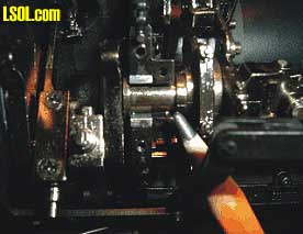 Crank Shaft Slip Joint The pencil tip is pointing to the slip joint built into the crank shaft. The crank shaft is made in two pieces. The front half of the crank shaft, driven by the front motor block, drives the valve gear. The back half of the crank shaft, driven by the rear motor, drives the cylinder connecting rods. The two halves of the crank shaft are jointed at the point indicated by the pencil. The one half of the crank shaft slips into the other half. The purpose for a two piece crank shaft is to eliminate a torque problem that plagued the Climax when it was first introduced. Bachmann solved the problem by using this two piece crank shaft. To the left in the above picture is the cylinder connecting rods. To the right of the picture is the value train eccentrics. Another example of insightful engineering. 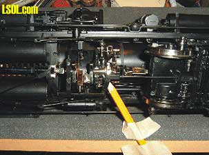
Additional View of the Split Crank Shaft Joint The crank shaft joint is held in place by a cover that provides support for the joint as well as protection. This joint is another place that will require lubrication from time to time. 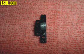 Split Joint Cover This cover is held in place by two small screws. While not easy to see in the picture, you can possibly just make out the metal insert in the left half of the cover that fits around the crank shaft. Something similar to an insert bearing in an automobile main bearing cap. The top half of the journal carrier also has this metal insert. Wear should not be a factor at this point on the crankshaft.
Just a few words and a picture or two on the rear end beam and its detail. This is the one big glaring mistake on this otherwise fine engine.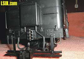
Rear End Beam Detail You will notice that the bottom of the rear sander sets too close to the L&P draw head. As built it is not possible to remove the pin from the draw head. If you plan to use the draw head with L&P rolling stock then a modification will be in order. I should mention that the cut bar was removed for this picture and in preparation to modify the location of the sander tank. Simplest solution would be to remove the draw head. The draw head is held in place with one screw off set to the right in the center pocket. Remove the draw head, remove the pin, install a short tow bar, re-install the pocket and you're in business. Or remove the sander tank and move it up higher on the tender. The sander tank can be removed by releasing it from inside the tender. There is a lug that holds the tank in place. Move the lug to a vertical position, remove the sander hoses, then wiggle the sander tank free. There is a second round mounting bracket molded on the tank. It is just pressed into a hole in the tender shell. Move the tank up enough to allow clearance for the L&P pin. The upper edge of the tender shell can be notched to accept the top mounting lug of the tank. The lower tank round lug can then be fit into what was the lower part of the upper mounting hole. Once in place the coal load can be replaced, sander lines reattached and you are in business. Also, as it comes from the factory the cut bar can not be raised as the coupler pin lifting arm hits the sander tank. Moving the sander tank to a higher position will allow the cut bar to be used if so desired. 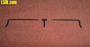
Cut Lever Detail The left and right side of the cut lever are metal. The center section with the lifting arm is plastic. Metal cut lever halves can be removed by gently pulling them from the plastic lifting arm center section. There are flats ground on the ends of the metal levers. These flats fit into the center section. Work carefully and the assembly will come apart. As I see it here are some positives and a few negatives for the Heisler. On the positive side would be the abundant use of metal for detail parts. It should be noted that couplers and their shanks are metal. The use of reduced size screws to assemble the engine gives it a very clean appearance. From what little I know about Heisler locomotives the "plumbing" seems to be correct. The use of plastic for back head detail and some external lines does not detract from the model. Air lines all seem to be correct and actually go someplace; not just left hanging out in space. Bachmann's solving the "torque" problem by using a two piece crank shaft is a plus. The list of positives could go on. On the negative side would be the mounting of the rear sander tank too close to the L&P draw head and the knuckle coupler cut lever. Bachmann's oversight on not installing a throttle. What's a Heisler engineer to do? Some folks have complained about a "clicking" noise in the drive train. The noise is not loud and would be covered by any sound system. This clicking sound comes when the crank shaft drops past center as it rotates. The faster the engine is operated the less the sound is heard. The sound is caused by the clearance that must be built into the crank shaft where the connecting rods and cylinder eccentrics connect. I don't really see any way to overcome this slight noise. It's a price you pay to have a fully functioning set of cylinders and valve chests. Should you decide to add a Heisler to the fleet I feel certain you will not be disappointed. 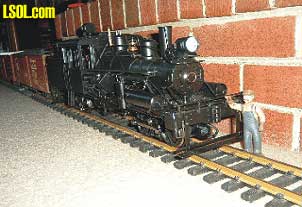
On The Ready Track Top of Page
|


