Power, Sound, R/C
:
Power Supplies
PICAXE Speed Controller High Power Modification with VIDEO
Feb 3, 2012
By David Bodnar
Author
Bio
While the original PICAXE based model train controller works very well and can operate most model trains, including fairly large G-Scale locomotives pulling as much as 3 amps, there may be hobbyists who need "more power!" In response to this need I have found an external H-Bridge that can be used with the original unit to provide 12 continuous amps of power with surges up to 30 amps!
Introduction While the original PICAXE based model train controller works very well and can operate most model trains, including fairly large G-Scale locomotives pulling as much as 3 amps, there may be hobbyists who need "more power!" In response to this need I have found an external H-Bridge that can be used with the original unit to provide 12 continuous amps of power with surges up to 30 amps!
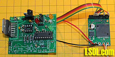
The modification to the circuit is very simple and it is not even necessary to make any changes to the controller or software. Not only will the external H-Bridge work with both versions of the circuit (the TV Remote Control version and the Train Recorder Version), you don't even need to remove the original L298N H-Bridge. All that is needed is a few wires that go between the PICAXE controller and the H-Bridge circuit board.
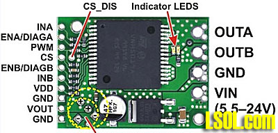
The Pololu VNH5019 Motor Driver Carrier The high power H-Bridge board is based on a chip that is designed for automotive use, the VNH5019A-E. In spite of its small size, the board is about 1" x 1.5" x 0.125", it can handle 12 amps of current continuously without a heat sink. That does not mean that it will not get hot as it can heat up to in excess of 100 degrees C if the current exceeds 12 amps. The board will shut down if the temperature exceeds 150 degrees C. It is also protected from reverse polarity and over voltage.
Wiring the Circuit Start by building the circuit as described here: PICAXE Model Railroad Speed Controller It is not necessary to install the L298N power IC unless you want to have both power options available.
Five wires need to be connected between the left side of the H-Bridge board and the PICAXE board. In addition the two boards need to share a common ground so power for the both boards must come from the same source.
Connect wires to the following pins on the H-Bridge board:
INA, PWM, INB, VDD and GND
These pins connect as follows:
INA to PICAXE board - pin 6 on the 18M2
PWM to PICAXE board - pin 9 on the 18M2
INB to PICAXE board - pin 11 on the 18M2
DD to the 5 volt pin on the 7805
GND to the ground pin on the 7805
To share the power between the boards connect the positive power pin on the input side of the 7805 on the PICAXE board to VIN (on the right hand side) and the ground pin to GND (on the right hand side).
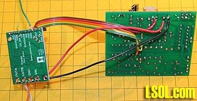
The photo below shows the boards wired together as described above. If you are planning on using the H-Bridge with high current loads you must use wire that is capable of handling such power. The wire shown below was used for testing only and will be replaced when used with more than a few amps.
The individual red and black wires that go between the two boards are the ones that need to be sized to the load. The five wires in the ribbon cable can be quite thin as they carry no significant current.
Video This video demonstrates the power board as it is used to power motors drawing up to 12 amps.
(right click on the box below and select Play)
Conclusion Even though most of us who use the PICAXE based motor control unit will not need the additional power that is described in this article it is nice to know that very high power trains or other devices can be operated with the PICAXE.