Power, Sound, R/C
:
Power Supplies
DC-DC Step Down Converter
Oct 24, 2011


By Dave Bodnar |
Author
Bio
There are many times when a model railroader needs to take a set DC voltage and reduce it to a lower voltage to operate some device or another. Come learn how it works and how to maybe build your own.
|
Introduction
There are many times when a model railroader needs to take a set DC voltage and reduce it to a lower voltage to operate some device or another. Perhaps you are operating from 23 volt lithium ion batteries and want to use a smoke unit that only works on 12 or 5 volts. Or your sound card will not operate from anything above 18 volts. If we were working with AC power, stepping down from one voltage to another is simply a matter of using a suitable step down transformer. We do this all of the time when we plug small "wall wart" power supplies into 110 volts and get a lower voltage from their output. Working with DC to DC step down conversion is more of a challenge as any voltage that is "lost" is typically dissipated as heat. A fixed value voltage regulator (like the 12 volt 7812 or the 5 volt 7805) will take any DC voltage up to 35 volts as input and will give you 12 or 5 volts. Unfortunately they have the potential to generate a great deal of heat. If, for example, you are operating a 5 volt smoke unit that draws 1 amp through a 7805 and start with 23 volts the voltage regulator must get rid of a great deal of power. Dropping from 23 volts to 5 is a drop of 18 volts. Dissipating 18 volts at 1 amp is 18 watts. This will quickly fry the 7805 unless you attach it to a very large, fan cooled heat sink. Even then it is likely to get too hot to touch. I wrote an article several years ago that shows how you can use a 7805 to give 5 volts for smoke units and similar devices. See: 5 Volt Power for Railway Electronics - even though the article deals with 7805 (5 volt) regulators most of the procedures shown will also work with other voltage regulators such as 7806 (6 volt), 7808 (8 volt) and 7812 (12 volt) units.
Another Way to Reduce Voltage
More sophisticated circuits can also be used to drop voltages using mosfets and special chips that use PWM (Pulse Width Modulation) to "chop" a voltage to a lower value. These are typically called switch mode power supplies. Most computers and laptops use switch mode power supplies. You can read more about how they work here: http://en.wikipedia.org/wiki/Switched-mode_power_supply . Recently very small, very inexpensive switch mode power converters have come onto the market. I would like to take the rest of this article to examine one such unit from SunTekStore.com. The same unit is also available from eBay (search eBay for DC-DC Converter Step-down adjustable). The SuntekStore unit can be purchased for less than $4.00 including shipping! The unit is a bit over one inch long and contains just a few components. The black devices with the silver tops are capacitors. The gold coil is a toroid that filters the output. The blue box with the screw on top is a potentiometer that is used to adjust the output voltage. Turning it clockwise increases the output voltage and turning it counterclockwise decreases it. Once an output voltage is set it stays the same even if the input voltage changes. This is a multi-turn pot that may require many turns of the screw to get to the desired voltage. 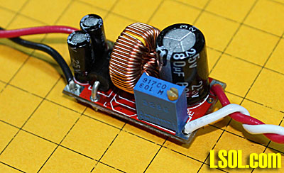
This view of the bottom of the unit clearly shows the terminals marked for input (IN+ and IN- on the right) and for output (OUT+ and OUT- on the left). The two 8 pin devices on the back are a P-Channel mosfet in the upper right area (see: http://datasheets.me/docs/ANPEC/000091.pdf ) and a DC Voltage Converter IC at bottom center (see: http://www.sparkfun.com/datasheets/IC/MC34063A.pdf ). 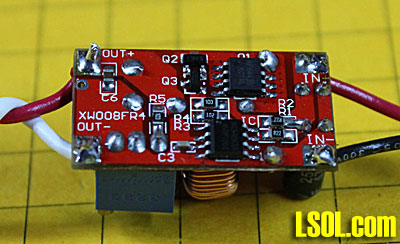
Here are the manufacturer's specifications: - Dimension: 31(L)x17(W)x13mm(H)
- Input voltage: DC 5-30V
- Output Voltage: DC 3-27V (adjustable, O/P Voltage < I/P Voltage by 1.5v, the default is 5V when delivery)
- Output current: Rated current 2.5A, max up to 3A(heat sink is required)
- Minimum Voltage difference: 2V
- Conversion efficiency: Up to 93% (O/P voltage higher, the higher the efficiency)
- Potentiometer adjustment direction: Clockwise (increase), counterclockwise (decrease)
- Operating temperature: Industrial grade (-40 ℃ to 85 ℃)
- Static power consumption is only about 6mA.
- Dynamic response speed: 5% 200uS
- Load regulation: ?? 1%
- Voltage regulation: ?? 0.5%
These devices have an adjustable output voltage and, as you can see from the specifications, take an input voltage of 5 --> 30 volts DC and produce an output voltage between 3 and 27 volts DC. The input voltage must be at least 2 volts higher than the output voltage. In other words, if you supply 15 volts DC your output voltage can be from 3 to 13 volts DC.
How Well Do They Work?
I ordered a unit from SuntekStore and have been putting it through its paces to see if these units can be used for model railroad applications. First I soldered wires to the two voltage input pads and the two voltage output pads. Note that both sets of pads are labeled + and - and this polarity must be maintained. Engines as Loads
I did some tests using Eggliners as test loads. When motors are used this is called an inductive load. The first three tests had two Eggliners on rollers. The second set used three Eggliners and the last series used three Eggliners and an LGB Rail Truck (I ran out of Eggliners!) The input voltage was fixed at 19.4 volts, the maximum that my bench supply would provide. The input current is the amperage being supplied by the bench power supply. The output voltage is the voltage on the output side of the converter. The output current was measured between the output of the converter and the connection to the test engines. I used an infrared thermometer to measure the temperature of the bottom of the board as the mosfet is what got hottest. Note that very little time (a minute or less) was given for the unit to heat up or cool down after changing the load settings. | | input voltage | input current | output voltage | output current | board temperature (F) | | Two Eggliners | 19.4 | 0.48 | 7 | 0.96 | 120 | | Two Eggliners | 19.4 | 0.74 | 10 | 1.18 | 122 | | Two Eggliners | 19.4 | 1.36 | 16.17 | 1.42 | 134 | | | | | | | | | Three Eggliners | 19.4 | 0.56 | 7 | 1.17 | 131 | | Three Eggliners | 19.4 | 0.91 | 10 | 1.43 | 141 | | Three Eggliners | 19.4 | 1.63 | 14.75 | 1.85 | 158 | | | | | | | | | Three Eggliners + Rail Truck | 19.4 | 0.62 | 7 | 1.34 | 140 (152 after several minutes) | | Three Eggliners + Rail Truck | 19.4 | 1.08 | 10 | 1.67 | 158 | | Three Eggliners + Rail Truck | 19.4 | 1.67 | 13.4 Maxed! | 2.0 | 178 | The item in bold type shows that the output voltage with three Eggliners and the Rail Truck would not go above 13.4 volts. This seems to be the limit of what the unit can handle with an inductive load. It is possible that it could be higher if a heat sink were applied to the mosfet to cool things down as we were approaching the maximum operating temperature (85 degrees C).
The photo below shows the test setup. The power supply is at top center and shows the input voltage and current in its two displays. The output is measured by the two meters at bottom center. When the photo was taken the two Eggliners on the right were connected and the two engines on the left were not. (To see how you can build a two meter voltage / current measuring device like the one I used see: http://www.trainelectronics.com/Meter_HF/index.htm ) 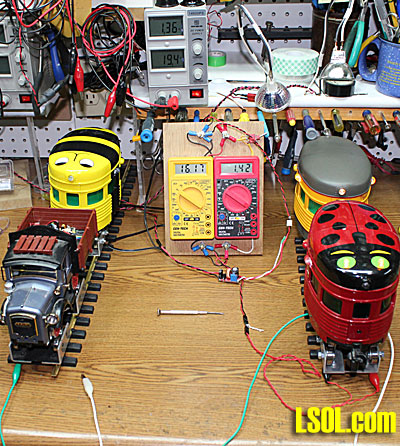
Incandescent Bulbs as Loads
I also tested the units using incandescent bulbs as loads. This is called a resistive load and is similar to powering a smoke unit that uses nichrome wire to heat smoke fluid. As you can see the unit maxed out with one 10 watt and one 20 watt bulb as loads. At that point it would only supply a bit over 10 volts and rapidly heated to over 200 degrees. | | input voltage | input current | output voltage | output current | board temperature | | One 10 Watt Halogen bulb | 19.4 | .2 | 5 | 0.53 | 122 | | One 10 Watt Halogen bulb | 19.4 | 0.31 | 7 | 0.6 | 126 | | One 10 Watt Halogen bulb | 19.4 | 0.45 | 10 | 0.76 | 128 | | One 10 Watt Halogen bulb | 19.4 | 0.61 | 12 | 0.82 | 129 | | Two 10 Watt Halogen bulbs | 19.4 | 1.21 | 12 | 1.64 | 142 | | One 10 Watt & One 20 Watt | 19.4 | 1.53 | 10.36 Maxed! | 2.2 | 212 |
Watch the Video
Observations & Conclusions
The DC-DC Converter worked very well in all of the tests that I did until it was faced with loads that drew more than 2 amps. Even though the documentation indicates it can handle 2.5 amps or more I think that may be a bit optimistic. At two amps it is a good performer. Above that the temperature gets to the point where the unit can easily damage plastic parts it comes into contact with. A heat sink might help but I would recommend keeping the load to no more than 2 amps. I also looked at the output on my oscilloscope and found that it is very clean, pure DC with very little ripple when running motors and light bulbs. For many of our lower voltage DC requirement this device may be just what is needed. The price, size and performance are all good. An Added Bonus!
After working with the device I thought about other things that one could do with it and came up with a really easy way to turn it into a dirt-cheap power controller for any DC operated train set (N, HO, G scale, etc). The potentiometer on the converter is adjusted with a small screwdriver and is a multi-turn pot that takes some time to adjust to a particular voltage. I noticed that the potentiometer is a 10K device and that its center terminal is shorted to one of the end terminals. That means that any linear 10K pot should work. I turned the pot's adjustment screw all the way to its lowest setting (all the way counter clockwise) and soldered an external 10K pot to the two connections on the circuit board. Doing it in this manner means that I did not have to remove the existing pot from the circuit board.
Now I have a quick turn speed control that can easily be used to operate any small locomotive (or two or three). All you need is a fixed voltage power supply (from an old laptop computer, for example) and you are in business! The blue oval shows where the external pot is connected. The external pot has three terminals. The center terminal and one of the side ones goes to the orange wire and the other terminal goes to the white wire. 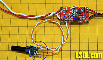
This close-up of the pot and the inset show you how the external pot is wired. The white wire goes to one of the outside contacts and the orange wire goes to both the center contact and the other outside contact. 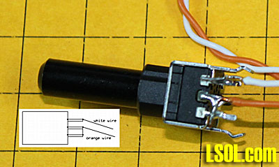
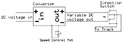
If you want to reverse the motor just put a properly wired DPDT toggle switch in line with the output as shown in the schematic. The only problem with this circuit is that the minimum power that the converter supplies is 3 volts so when the potentiometer is at its lowest speed setting the engine is still getting a small voltage. For most of our trains that will not be an issue as they don't move at 3 volts. If you are running smaller scales you will need to use an on/off switch to completely stop a train or use a DPDT switch with a center off position to remove all voltage from the track. 
Click for Larger Image
| DC-DC step down converter. |
| Very nice, it appears that the limit is around 2 amps output and it seems to generate heat. Interestingly the output amperage is more than the input amperage and of course that is explained by the higher voltage. The input wattage (VxA) will always be higher than the output wattage, (laws of entropy and all that) I didn't go to all the web sites yet, so I have 2 questions. First: am I to understand that the output is pulsed DC or is it actually "switched" to a constant voltage? Second: is the voltage control unit electrostaticly sensitive? Thanks for the article and your testing of this new unit. |
| Glenn Habrial - 10/24/2011 - 21:21 |
| Step Down Converter |
| David, thanks for another well-written interesting and useful article. The photos are helpful too. The tables of voltages and currents will be useful to anyone considering using the device. |
| Bill Ness - 10/26/2011 - 18:32 |
| step down supply |
| Dave thanks for sharing this device with us. I do plan on adding constant lighting to my passenger cars, and this little gizmo would really do the trick. I would just need a bridge rectifier and my 3 volt light bulbs or LEDs and my cars could be lit at any track voltage above say 5 volts. With a suitable capacitor the lights could even stay on a while after the power was turned off. I do suspect that this device wouldn't work too well on PWC power, maybe thats a follow on article. Thanks Dave Glenn, the torrid filters the output, and Dave stated that the output was very smooth, not pulsed. Another bonus. |
| David A. Maynard - 10/26/2011 - 18:36 |
| DC-DC Cibverter |
| Glenn - As David noted the output is very clean, almost pure, DC. The large toroid is the main component that removes what little ripple there is after conversion. I don't think the unit is any more sensitive to electrostatic damage than most circuits - I had no problems and didn't see anything noted in the documentation. I haven't tried it on PWC but it should work in a similar manner. I'll give it a try and see what happens. dave |
| David Bodnar - 10/27/2011 - 07:36 |
| smooth voltage and ESD answers |
| Dave and Dave: Thanks for your answers. |
| Glenn Habrial - 10/27/2011 - 10:49 |
| DC-DC Cibverter |
| After this article was written a question came up about using PWM (also called PWC) voltage input for the DC-DC converter. I wasn't sure that it would work properly so I put together an experiment to see if it would work or not. I used an Aristo Craft Revolution receiver as a source of PWM DC. I powered the Revolution from a bench power supply set to 16 volts. The output of the Revolution connected to the input of the DC to DC converter making sure that proper polarity was observed. I initially set the Revolution's transmitter for 50% power and confirmed a 50% duty cycle wave form on the oscilloscope. I connected a small hobby motor to the output of the converter and found that the motor began to turn. Adjusting the potentiometer on the converter changed the voltage output and the motor speed. Even when I decreased the power on the transmitter the converter struggled to maintain the set voltage. Since PWM supplies pulses at the full voltage of the input this makes sense. The available power was decreased when the % power was lower but, so long as the motor was small, the set voltage was maintained. More testing may be in order but this simple exercise answers the basic question that was posed. The answer is YES, this DC to DC converter will work with PWM input. |
| David Bodnar - 10/27/2011 - 11:24 |
| PWM control and DC output |
| wow that is good to know. That expand's it use to other items. |
| Glenn Habrial - 10/27/2011 - 13:39 |
| Wish List |
| This unit will be useful for sure. Now if someone could just make a similar DC-DC step-UP power supply. . . . I'd like to make 12VDC from varying track power, even when it is low. |
| Ralph Walker - 10/31/2011 - 10:56 |
| DC-DC Up Converter |
| Ralph - I just received such a unit for evaluation - may write up some details soon..... dave |
| David Bodnar - 11/02/2011 - 02:01 |
| printer friendly? |
| Hi Dave: I could not get the Printer friendly to work. It would not print. Could it be that because I am using a MAC comp? Thanks EMIL |
| Emil Tancredi - 11/09/2011 - 03:17 |
| Printer |
| Emil, I will contact you by email about the printer copy |
| Peter De Keles - 11/09/2011 - 09:53 |
Top of Page
|