In the News
Exclusive: Outside/In! Aristo Trackside Receiver for Revolution
Jun 2, 2010


By David Bodnar |
Author
Bio
As you may know I have been working with Aristo Craft for the last few years as the Revolution radio control system was being developed. I recently received a prototype of the latest part of the system, the trackside controller, also referred to as the base station.
|
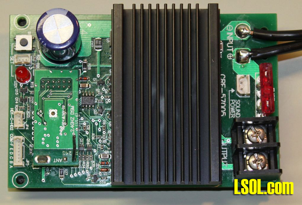
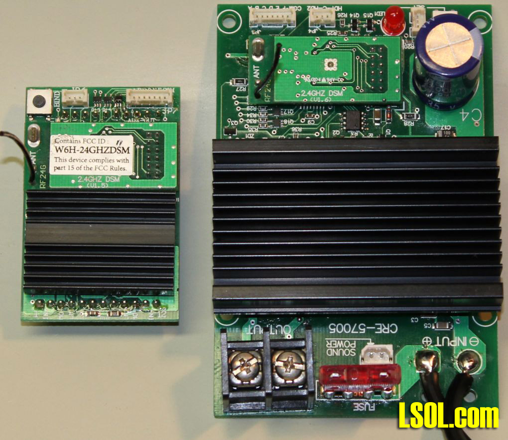
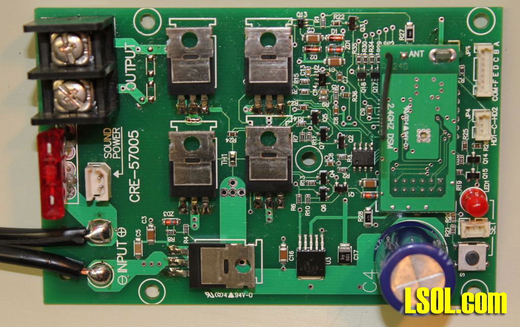
As you may know I have been working with Aristo Craft for the last few years as the Revolution radio control system was being developed. I recently received a prototype of the latest part of the system, the trackside controller, also referred to as the base station. This unit is a major component that many of you have been waiting for. It allows you to control track power to your railroad with the Revolution transmitter and gives you the basic functionality of the original Aristo Craft Train Engineer and much, much more. Click image for Larger View 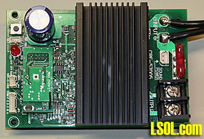 Hardware Overview The trackside controller is very much like a larger version of the on-board controller. It is 4 1/8" x 2 3/4" and 1 1/2" high. Click image for Larger View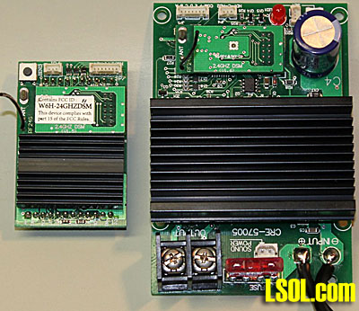 As you see there are many similarities but there are also major differences.
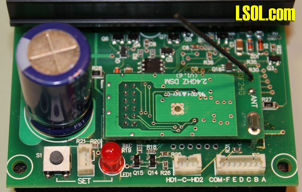
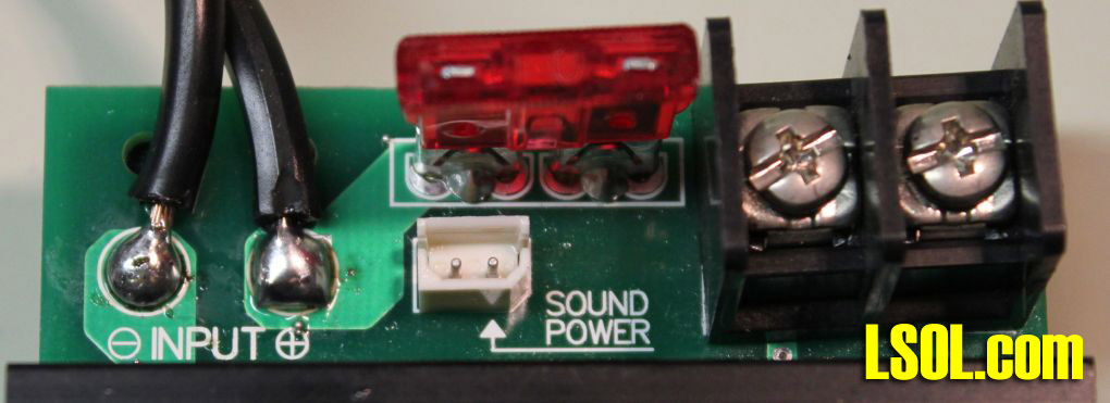
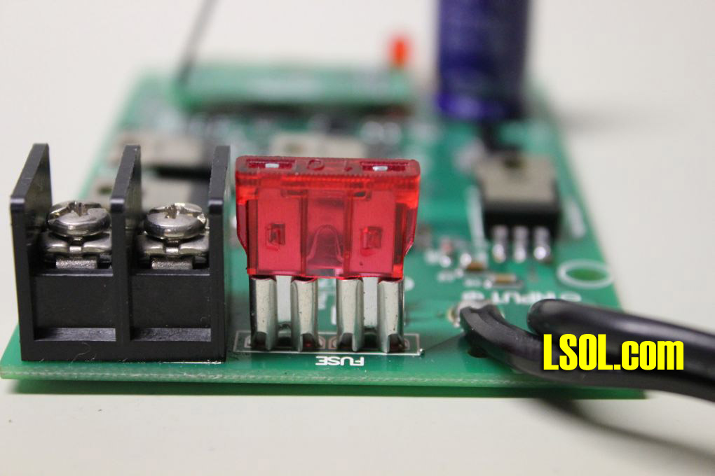
The similarities include a seven pin auxiliary interface connection, a three pin connection for front and back lights, a three pin set button connection (for external mounting of the link switch - it is labeled "SET" on the board) and a link switch that is mounted directly to the board. Note that in normal trackside use you are unlikely to use the external link switch connection, the auxiliary interface or the lighting connector. For on-board or power car use these connections will come in very handy. In this photo you can clearly see the small receiver board (which is identical to the one used on the other Revolution receivers), the link button, link LED and the three connectors. The connector to the left is for a remote link switch, the one labeled "HD1-C-HD2" is for front and rear lights and the one labeled "COM - F E D C B A" is for auxiliary functions. Click image for Larger View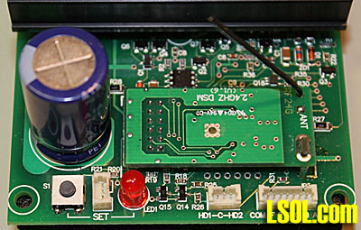 The differences between this board and its smaller brother are significant. Unlike the on-board Revolution receiver, there is no circuitry that will allow you to connect the power to the board without regard to polarity. There are two wires soldered to the circuit board that connect to your fixed-voltage DC power supply. You must connect the positive connection from your power supply to the positive (red) wire that supplies power to the board and the negative connection to the negative (black) wire. One very important point needs to be made about connecting with reverse polarity. This controller is unusual in that it is designed so that it will not work AT ALL if the polarity is incorrect. This means that if you connect it backwards it just sits there, does not blow the fuse, does not do any damage. This is a really nice design for those of us who make connection errors from time to time! Rather than having wires or small terminals that connect to a locomotive's motor, like the smaller receiver board, there are two large screw terminals that are used to connect to the wires that go to the track. This photo also shows the "SOUND POWER" connection that can be used to provide power to your sound card. It provides the exact same voltage to the sound card that comes in through the power input cables. The pin on the left is negative and the pin on the right is positive. This power connection is made after the fuse so it is protected by that device. Click image for Larger View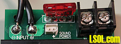 The fuse that is used is similar to the one on the original Train Engineer. This is a common automotive spade (or blade) fuse and can easily be found locally at hardware and auto-parts stores. I'll have more to say about this later on. One of the most noticeable differences is the size of the heat sink that cools the circuitry. As you can see from the photos it takes up about 1/3 of the board and measures 2 3/4" x 1 5/8" and is over 3/8" thick.
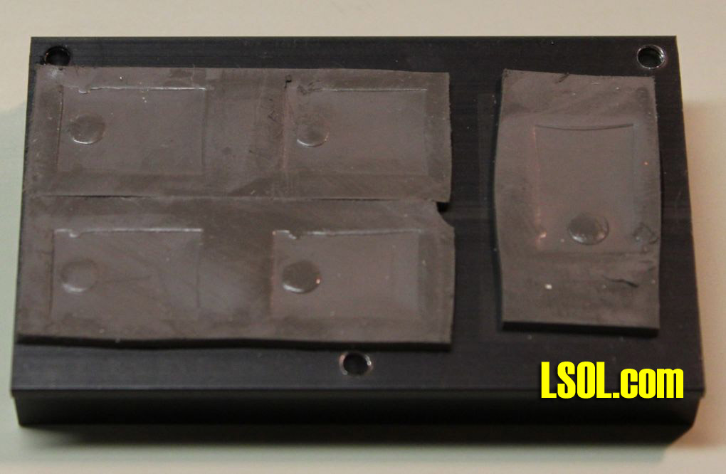
Hardware Setup for Trackside Use If you are going to use the trackside controller to operate a loop of track setting it up should take only a few minutes. You need to make only four connections. The red wire that comes from the controller's circuit board goes to the positive connection on your power supply and the black wire goes to the negative. The wires from your track go to the screw terminals. That's it for the wiring! A Word About Power Supplies and Wire Size The trackside controller will operate trains from 0-4-0 starter sets up to large, powerful A-B-A diesel systems pulling dozens or scores of heavy weight cars. You need to pick a power supply that will fit your current and future needs. I would suggest starting with at least a 10 amp power supply. I always recommend purchasing a power supply that has more capacity than what you expect to use as many garden railroaders start out with a too-small power supply and replace it in short order. You also need to run wire between the power supply and the controller and between the controller and track that can handle the expected load. The wire that is supplied to go between the controller and the power supply is number 16 stranded wire. The wire that you supply to go between the controller and the track should also be at least number 16. If the distance from the controller to the track is more than a dozen feet you may want to go to the next larger size, number 14 wire. Remember, you will not have problems using wire that is too thick, but wire that is too thin can heat up and rob your layout of power. Where to Put It You will note from the photographs that the unit is shipped without a case. I asked Aristo Craft about the decision to market the controller this way and their response was that the board is designed to be housed either within a trackside building, inside of a locomotive or in a trailing power car. Two 3/8" thick pieces of foam are glued to the bottom of the board to protect it and to guard against short circuits. Click image for Larger View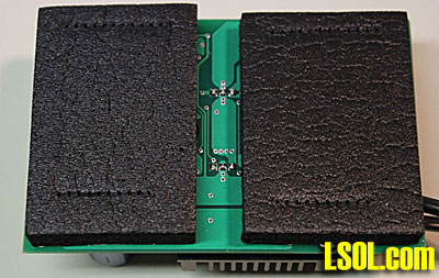 The unit is small enough to fit inside of just about any trackside building or structure. Just make sure that the controller and power supply are protected from dirt, rain and excessive moisture.
Setup and Use with the Transmitter Configuring the transmitter to operate the trackside base station is very similar to configuring an on-board controller. Here are the steps one needs to follow. Please see the articles on the Aristo Craft web site for a more detailed description of the various options as this is not meant to be a complete tutorial, just some notes for those who are already familiar with the Revolution. Connect power to the controller and fire up the transmitter. Press the MENU button. Under ASSIGN FUNCTIONS do the following: -
select a bind address - if this is the first unit just use the default value, 00 -
select RxType - BASE RX -
choose an appropriate NAME -
PWR MODE can be either PWC or LIN - it makes no difference (see section below) -
Leave MOMENTUM, DELAY, MOTOR, TOP SPEED and START SPEED set to their default values - these can be changed later. -
Push and hold the LINK button on the trackside controller until the LED flashes then select LINKING on the transmitter - in a few moments you should see LINKING PASSED! Press the MENU key to return to the main menu Under ADD MU/SU CAB do the following Press the MENU key to return to the main menu then press MENU again to return to the main control screen Use the <<T and T>> buttons to select the CAB # that you are using for the controller. You should see LinkOK at the bottom of the screen. You can now use the up and down arrows to control speed and the left and right arrows to control direction. If you already have experience with the Revolution it is a snap!
PWC or LIN When the Revolution was first introduced the software to control the trackside controller was already installed in the transmitter. If you selected BASE RX as the type of receiver there was an option that allowed you to choose either LIN or PWC as the Power Mode. This would give you the same functionality that you have with the old Train Engineer which has a switch that allows you to choose either Linear or PWC (Pulse Width Control, also called PWM for Pulse Width Modulation). The linear mode supplies traditional DC power that ranges from 0 volts when off to the maximum voltage offered by your power supply when at top speed. PWC uses a series of very rapid pulses of full power to regulate the amount of power that goes to the locomotive's motor. PWM/PWC has a number of advantages over traditional DC power on our railroads. It has the potential to provide more power to motors and sound cards at low speed and its use can cause lights to be brighter and smoke units to work better at lower speed settings. When I received the new trackside base station I set it up for PWC for my first round of tests. Everything went well and I reset the system for Linear mode and re-linked the receiver just to make sure the change was recognized. Again the locomotive worked as expected. As a matter of fact it worked exactly as it had before. This gave me pause as there should have been some difference in acceleration or low speed operation between the two modes. The only way to be sure that the system was using linear mode or PWC mode was to hook the output from the controller that normally goes to the track to my oscilloscope. The wave forms on its screen would tell the story. The series of pulses that I saw in both modes told me that no change had taken place between the PWM/PWC and the LINear setting. Both were using Pulse Width Control as both clearly showed square wave patterns that changed in width as the speed increased. I sent off an email to Lewis Polk from Aristo Craft asking about this and he responded that a decision was made to eliminate the Linear mode as PWM/PWC was the modern way to control model trains and that linear was outmoded. I can't say that I disagree with this decision. After all, PWM/PWC is used by the existing Revolution receivers and on virtually all DCC systems. It has been used for many years and the only problems that I have seen reported were with obscure and obsolete sound systems that could be overheated by its use. I use PWM for many of my TrainElectronics.com projects and have never heard a report of it damaging a large scale locomotive.
Test Data The unit is designed to operate on an input voltage between 12 volts and 30 volts. I tested it without any problems from 30 volts down to 12 volts and it worked perfectly. I continued my tests clear down to 8 volts then down to 6 volts and, even though the locomotive barely ran, it continued to work without a problem. That is quite a range! Continued testing proved to me that the Mosfets (power transistors) that are used on the board are very efficient. By this I mean that the output voltage that they deliver to the track is very close to the input voltage that they receive from the power supply. The smaller the voltage loss within the circuitry the cooler things run. This low voltage loss is due to the low internal resistance of the Mosfets that are used in the Revolution. Here are some specific measurements that I made. All tests were done with a variable bench power supply with a small locomotive as a load. The transmitter was set to 100% speed. During the first five tests the locomotive was drawing about 1 amp. The last test was with a 7 amp load. | Input Voltage | Output Voltage | Difference | Efficiency | | 24 | 23.23 | 0.77 | 96.8% | | 18 | 17.26 | 0.74 | 95.9% | | 12 | 11.45 | 0.55 | 95.4% | | 8 | 7.57 | 0.43 | 94.6% | | 6 | 4.94 | 1.06 | 82.3% | | 7 amp test | | 24 | 20.8 | 3.2 | 86.7% | These numbers demonstrate why the controller can handle 15 amps without needing a fan on the heat sink. Even in the second test where the controller was passing 7 amps at 24 volts the voltage drop was only 3.2 volts. During that test I was running six motor blocks (5 small locomotives and a very large bare motor block) wired in parallel under a medium load. The test ran for about 10 minutes. At the end of that time the 8 amp power supply was hot, all of the motor blocks were warm and one was quite hot. The good news is that the heat sink on the controller was just warm to the touch. On-board Use A number of the features of the trackside controller make it ideal for use on-board locomotives or in a trailing power car. It is small enough that it will fit inside of many locomotives and its power output allows connection to a powered A-B-A unit with current capacity to spare. If you do plan on putting such a load on the controller make sure that you run heavy gauge wire between the locomotives and allow space for air to circulate around the controller's heat sink. The auxiliary output connection is the same as on the original on-board unit and can be used to control sounds, smoke and other features. As I mentioned earlier, there is a dedicated plug labeled "sound power" that can be used to supply power to the sound card.
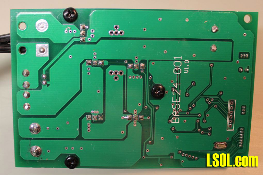
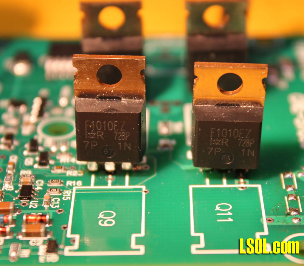
Fuses When I received the prototype unit it had a 10 amp spade fuse installed. I asked Lewis Polk about this and he told me that they used that fuse on my unit because it was what they had on hand. Shipping units are likely to have a 15 or 20 amp fuse installed. That got me thinking about what size fuse you should be using on this controller. Click image for Larger View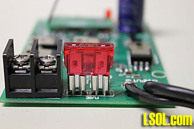 My personal recommendation would be to use a fuse with a rating that just exceeds the current draw that you are likely see on your railroad. Think of it this way, if the unit comes from the factory with a 15 or 20 amp fuse and you are only running a single locomotive that draws, at most, two amps what will happen if that train derails and shorts the track? The fuse will allow 15 or 20 amps (at 24 volts that is 360 to 480 watts!) to pass through the system, your wheels, track & cables before it blows. That is a lot of power and it has the potential to do damage to your equipment. If, however, you use a 2.5 amp or even a 5 amp fuse it will blow more rapidly and will help to reduce the potential for problems. Under no circumstances would I use a fuse that is larger than the output from the power supply. If you are powering the system with a 10 amp power supply and you have a 15 amp fuse in the controller it will NEVER blow! You will, hopefully, blow the fuse on the power supply but why take a chance? An Inside View For those of you who, like me, always want to know more about what is under the hood, I partially disassembled the controller and photographed the components that reside under the heat sink. First I had to remove the two foam pads that were glued to the back of the board. They were held on by double sided tape and, with the help of some Goo Gone, came off fairly easily to expose the bottom of the circuit board. Click image for Larger View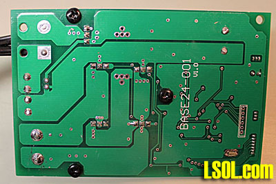 The three black screws seen above hold on the heat sink. After removing them the heat sink comes off easily and the power components can be seen. The five devices whose silver heat transfer tabs face us are N-Channel Mosfets. They do all of the work to turn the unit into a full blown power controller.
You might ask why there are five Mosfets since most controllers use only four. The top four Mosfets make up an "H-Bridge" which is the electronic equivalent of a double-pole-double-throw switch. The fifth Mosfet at the bottom turns the system on and is responsible for making sure that you have the power supply connected correctly. It keeps the system completely off until it sees that the power supply is connected positive to positive and negative to negative. Click image for Larger View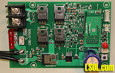 The five Mosfets, IRF1010EZ's from International Rectifier, are all the same and, if properly cooled, can handle 60 or more amps each! Click image for Larger View There is a thermal pad between the Mosfets and the heat sink. It can be seen in this bottom view of the heat sink. The indentations from the backs of the Mosfets can be clearly seen. Click image for Larger View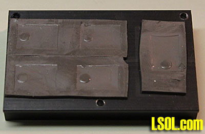 Conclusion It looks like Aristo Craft may have another winner on its hands. The trackside base station controller is a major addition to the Revolution family. I am sure that it will find a home on many of our personal and club layouts. The controller should be available later on this summer at a list price of $200 for one or a six pack for $1000. Most retailers are likely to sell them for less than $150 in single quantities. I hope you have an opportunity to give this unit a workout soon.
| PWM |
| I agree that pulse width modulation is the way to go if you can. I did have a Sierra sound board fail when running PWM, but the same sound board had worked flawlessly for months on linear power. Also some sound boards use the voltage, on the rails, to select what rpm sound to simulate on diesels. Before using any sound system on PWM check the information supplied with the sound card and manufacturer's recommendations. |
| David A. Maynard - 06/02/2010 - 15:02 |
| Accessory Receiver |
| Is there anything on the horizon that will allow the Revolution transmitter control of turn outs? Thanks Barry Harris Laurel Creak and Western Railroad |
| barry harris - 06/02/2010 - 22:02 |
| Accessory Receiver |
| Barry - I did a workshop on the new device (it is in the video LSOL library) that does turnouts - it should be available later on this year. dave |
| David Bodnar - 06/03/2010 - 13:29 |
| Trackside Receiver |
| David, after I conversation about the basic revolution, how does this item fit into the equation? |
| Ron Hill - 06/04/2010 - 20:34 |
| Trackside Receiver |
| Ron - not quite sure I understand your question so I'll answer it as best I can. Aristo is recommending that this unit be used primarily as a high current receiver to be mounted inside of a locomotive or trailing car. Personally I think it will find more use as a trackside unit as a replacement for the original Train Engineer. Hope that helps. dave |
| David Bodnar - 06/05/2010 - 14:35 |
Top of Page
|