Since Kadee couplers are so popular with many large scale operators I thought it might be interesting to install a pair on the LGB Genesis. The Genesis, with its pivoting pilot/snow plow, adds another dimension to a Kadee installation. 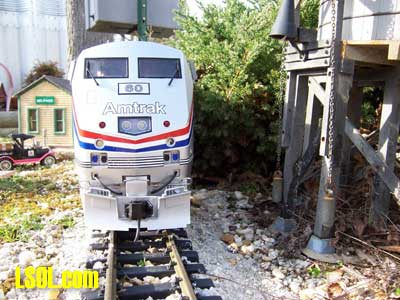
BACKGROUND AND KUDOS
Before proceeding with the Kadee installation details, I must first acknowledge the great interest shown and assistance received from Sam Clarke. Sam Clarke, Conversion Specialist, Artist/Illustrator, and Research & Development guru at Kadee Quality Products Company is without doubt a most valuable resource for the model train hobbyist.
I was a little hesitant to contact Sam for assistance not knowing what type reception my questions would receive. Sam went out of his way to provide his expertise while at the same time answering my questions in a timely and clear manner. My experience with Sam was most pleasant and beneficial.
Since the Genesis is so new, Sam had yet to see the locomotive up close and personal. We agreed that the installation of a Kadee coupler on the front pilot could present a new set of challenges.
In order for Sam to have a better idea of what could be required I sent him the front pilot so he could see first hand what was involved with an installation. In a matter of just a few days Sam got back to me with his recommendations along with possible Kadee coupler configurations.
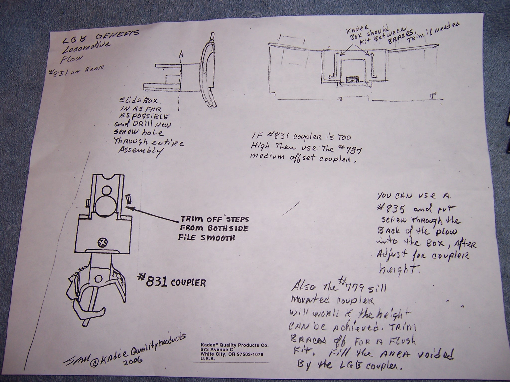
Sam even went so far as to provide a detailed drawing that outlined and recommended a installation protocol for the front pilot. It was a pleasure to deal with Sam.
Other large scale manufacturers and suppliers would do well to emulate Sam's and Kadee's commitment to the hobby. Thanks Sam, you made the installation a most pleasant process.
Kadee couplers are available at a signigicant discount through the LSOL site www.kadeecouplers.com You can also visit the Kadee site at www.kadee.com for additional product information and specifications.
LET'S GET STARTED
For this installation I wanted to retain the capability of the Genesis coupler system to pivot the front and rear coupler assemblies for handling tight radius curves. It is evident that LGB was cognizant of its customer base and the need to design a locomotive that could handle the tightest radius curves.
With this goal in mind, Sam provided recommendations as to type coupler for both front and rear installation. Sam provided a selection of couplers as possible candidates for installation.
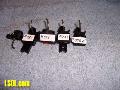
Pictured are the couplers as supplied by Kadee. Each coupler is tagged with its part number.
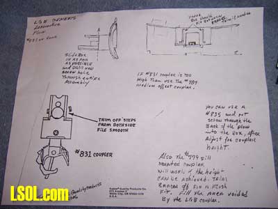 Click for VERY BIG picture of the above drawing.
This is the diagram Sam provided. After inspecting the Genesis front pilot Sam came up with the sketches and recommendations of possible candidate couplers. This diagram was most helpful, especially for the front pilot installation.
REAR COUPLER INSTALLATION
For the rear coupler it was decided to install a Kadee #831 assembly. This turned out to be a good choice with installation being straight forward and easy to accomplish.
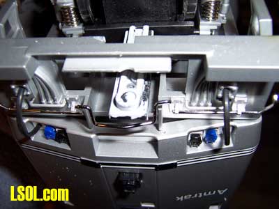
Pictured above is the rear draw bar with the LGB coupler removed. The draw bar is attached to the top of the motor block. The draw bar will pivot side to side and incorporates a self centering spring.
While this is a good solution for operating on tight radius track, the draw bar has some up and down looseness. This up and down movement could cause a problem with the coupler over riding the following car's coupler. Since putting the Genesis into service this up and down movement has caused just two separations.
I have yet to operate the locomotive with the Kadee couplers. There may be a solution to eliminate the looseness. I did not take the time to investigate further. 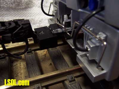
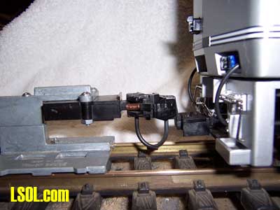
Initially a #831 coupler assembly was installed, as pictured above. This is a rather easy, quick installation. To install the #831 the only requirement is to drill a new hole in the locomotive's draw bar.
This hole ends up being just to the rear of the lower pilot cross piece. The mounting screw tip is visible just to the front of the cut lever. No shimming of the coupler was necessary to obtain correct coupler height when checked against the Kadee coupler gauge.
This picture depicts the relationship of the coupler box to the rear pilot. Note the space between the coupler box and the rear pilot. While the coupler will certainly work with this mounting, I did not like the excessive space between the rear of the coupler box and the rear pilot.
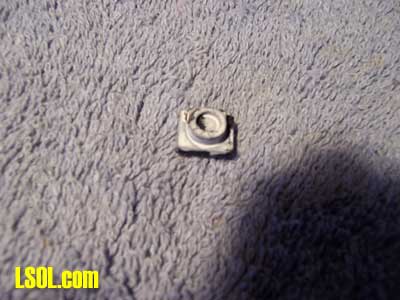
In order to move the coupler box closer to the pilot it was necessary to shorten the draw bar. The draw bar was shortened 7/16 of an inch. Pictured above is the piece cut from the rear draw bar. 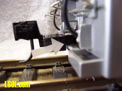
These two pictures show the coupler box in relation to the rear pilot. Shortening the draw bar moved the coupler box almost against the pilot. By shortening the draw bar the original hole that attached the LGB coupler can be used to mount the #831 coupler. The length from the rear pilot to the end of the coupler knuckle is within 1/32" of the length when the LGB coupler was in place.
The coupler gauge matched up with the rear mounted coupler. It was not necessary to use any shims to obtain a height match.
FRONT COUPLER INSTALLATION Now the "fun" began.
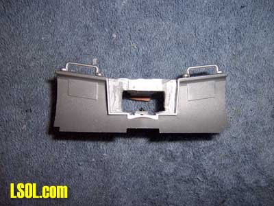
The front pilot/plow along with coupler was removed. First choice was to try installation of a #831 that would have matched the rear installation.
Inserting the #831 into the front pilot demonstrated that the coupler box would set in front of the pilot. Placing the assembly on the front draw bar was somewhat difficult and the results did not look good with the coupler box totally exposed in front of the pilot. Not a good choice!
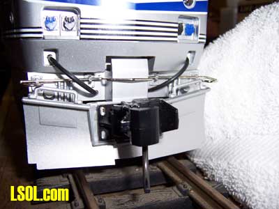
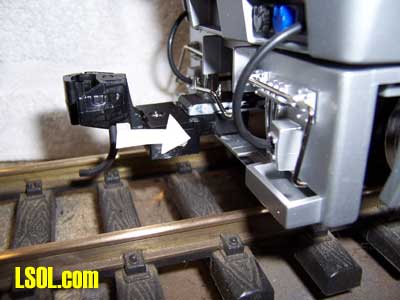
Next choice was to test fit the #779 coupler assembly as shown above. The #779 is a end beam mounted coupler with a straight coupler shank. With the straight shank, coupler height was too low to align with the height gauge. So, a #836 medium offset coupler was installed in the end beam mount box.
This is the end beam mount with the #836 installed. The coupler now matches up with the height gauge. Using this combination would make front coupler installation a simple matter.
The coupler draw bar would have to be cut off so it is at least flush with the pilot. The end beam mount could then be bolted to the pilot/plow.
Should this installation be used I would recommend adding a second fastener to the pilot/plow tangs that secure the assembly to the draw bar. Use the existing mounting hole for a mounting screw and drill a additional hole all the way through the bottom tang, coupler shank, and top pilot/plow tang slightly to the rear of the mounting screw. Use a bolt of sufficient length to go through from top to bottom of the assembly. A 2-56 bolt and nut can be used to make this attachment.
With this coupler assembly in place the length from the face of the pilot to tip of coupler was the same as that of the LGB coupler. Using this arrangement does not set the end of the coupler at a greater distance from the pilot. So, if the existing LGB coupler length does not bother you then the modified #779 should do the job.
I still wasn't satisfied with the solution for the front coupler. Next step was to try to fit a coupler box into the pilot/blade. For this installation a #835 Modified supplied by Kadee was considered. This turned out to be the solution for the front coupler.
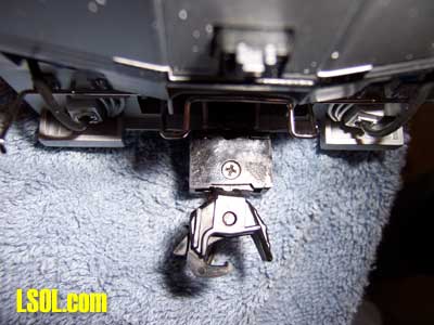
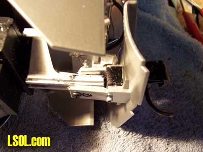
To install the #835 Modified it is necessary to do some major cutting of the pilot/plow. It is necessary to open up the pilot in order to insert the coupler box. For me, and the faint of heart, this is a task not easily undertaken. The above picture shows the pilot modified to accept the coupler box.
This takes some major surgery and I recommend you proceed slowly double checking each cut before it is made. Trick here is to open the pilot for the box without destroying or weakening the pilot tangs that secure it to the coupler shank. Proceed with caution on this installation. I found it was also necessary to further cut back the coupler draw bar slightly and to remove some material from the front top of the draw bar in order to get the coupler box fully seated in place. 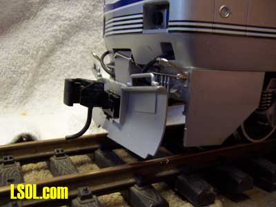
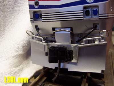
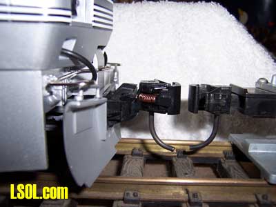
These two views show the #835 Modified in place. According to Sam the coupler I used is actually a #836 coupler with a medium offset head. In the process of fitting and adjusting coupler height I took the #835 and replaced it with a #836. What you need for this installation is a coupler box without a mounting shank.
The coupler box is attached to the pilot with a 2-56 bolt and nut placed down through the rear hole in the coupler box. You'll have to drill a hole through the upper and lower pilot tangs. I positioned the coupler box in place and then drilled down through the upper tang, passing through the coupler box mounting hole and then through the bottom tang.
Once the coupler box is attached to the pilot the pilot is placed on the coupler draw bar. A 2-56 bolt and nut are used in place of where the original coupler mounting screw was used. It will be necessary to drill up through the existing bottom tang hole, coupler shank hole, and through the upper mounting tang. Insert the 2-56 bolt through this hole and secure with a nut. A second hole should be drilled just to the rear of this mounting bolt. This hole should be drilled through the bottom tang and through the coupler shank. Use the original coupler mounting screw in this hole to securely fasten the assembly to the draw bar. Attached in this way the front coupler should be able to sustain any load.
This is a side view, under the engine of the pilot mounted to the draw bar. It is necessary to use a spacer on top of the draw bar to fill the void once taken up by the original knuckle coupler. My installation isn't pretty, but it works.
You'll note that I had to use 2-56 bolts with an allen head. Five hobby shops in the area and not one with hex head brass bolts and nuts!
FINAL THOUGHTS As it turned out the installation wasn't all that difficult. Cutting the front pilot and fitting the coupler box took the most time and contributed to the majority of the bad language. Once in place you will find it necessary to check for obstruction under the front of the locomotive.
The object is to complete the installation in a manner that will allow the front coupler and pilot to swing freely from side to side just as it did with the original LGB coupler. You no doubt will find that some small amounts of under frame material will have to be cut away or filed down to gain an unobstructed range of motion.
For your consideration. An alternative, if the locomotive will be operated on larger radius curves, would be to eliminate the draw bar swing from side to side. The front and rear pilots could be permanently attached to the locomotive. Then body mounted Kadee couplers could be used.
In this way the coupler boxes could be tucked in under the locomotive in a most prototypical manner. This method would take a little more work and some work bench engineering but the result would be one great looking set of couplers very close to the 1:1 Genesis.
Happy coupling.
| Body mount Genesis KD's |
| I think I want to body mount the couplers to my LGB Genesis. How do I access the rear swinging pilot to stop the swing? Do I have to remove the body? What about the front? Is it easily accessed? I just put the unit on the bench and Sam sent this article to me, so I haven't done anything but remove the rear coupler so far. |
| Bill Muller - 08/29/2008 - 19:43 |
| Body Mounting Couplers |
| Bill, Since you have the Genesis you can see that both the front and rear pilots will have to be fixed to the locomotive. To do this the best way appears to remove the body to accomplish the task. You'll have to figure out a way to attach the front and rear pilots and then proceed from that point. When the Genesis first came out there were a number of folks that fixed the pilots to the locomotive. I have no detailed information on just how they accomplished the task. But it can't be that difficult. When you finish the conversion, come back here and fill us in on how it was accomplished. JD |
| JD Miller - 08/29/2008 - 20:43 |
Top of Page


 Click for VERY BIG picture of the above drawing.


