Scratch & Bash
:
Engines / Rolling Stock
How to: Bachmann Mogul Cab Upgrade
Apr 6, 2005


By Jon D. Miller
LSOL.com Reviews Editor |
Author
Bio
An easy modification to bring the little engine more in line with 1:20.3 proportions is to install a larger cab. There are several suppliers of well designed, easy to assemble, laser cut wood kits.
|
Bachmann's Industrial Mogul has proven to be a rugged little engine for very few out of pocket dollars. The steam profile "Indy" locomotive is advertised as being 1:20.3 scale. There are those that question the engine's scale even though it is modeled after a industrial locomotive that by its very nature was rather small. An easy modification to bring the little engine more in line with 1:20.3 proportions is to install a larger cab. There are several suppliers of well designed, easy to assemble, laser cut wood kits. Two of these suppliers are: Banta Modelworks www.bantamodelworks.com and FH&PB Railroad Supply Company www.nmia.com/~vrbass/fhpb. Both of these manufacturers offer a selection of cabs for large scale locomotives. You can visit their sites to view the various kits available that enhance a number of different large scale steam profile models. I selected a kit produced by Banta Modelworks. I liked the look of the locomotive with its new cab that Banta had displayed on their web site. The "Indy" kit sells for less than $50.00 and that includes shipping. You will find making the conversion is a rather easy task. Assembling one of these well made kits could be a good first step for anyone that is considering enhancing the "Indy" with a cab upgrade. Experience gained in putting together one of these laser cut kits is a good way to "get your feet wet" for additional more advanced kit construction or scratch building equipment. So, let's get started. The Banta kit contains two sheets of rather simple instructions. The kit is very basic so that detailed step-by-step construction plans are not required. 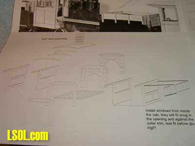
Photo quality of the two instruction sheets is not that clear. However, you should be able to see that parts are clearly marked and assembly will be rather straight forward. There are also several pictures of the completed cab and tender coal boards that will aid with assembly. 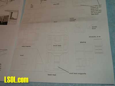 The first step will be to remove the existing cab. You will find there are tabs at the four corners of the cab floor that hold the cab in place. Depressing these tabs will release the cab from the cab floor. You may have to wiggle the cab a little to get it to come free from the slot where the front cab wall fits around the boiler. Also, there are two lines that enter the cab. One, on the right side is a feed water line. The line on the left, while it appears to be a feed water line, goes to the smoke box so it must represent some type of exhaust line. Both of these lines can be moved forward or taken off the engine to aid in cab removal. 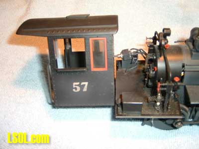
This is what you end up with when the cab is removed. Note one of the cab mounting tabs just to the rear of the engineer's seat box in the lower left hand corner of the cab floor. There is another one on the other side just behind the DPDT switch. On an unmodified engine this tab would be behind the fireman's seat box. There is a floor tab on each side of the firebox that secures the front of the cab. Once the cab has been removed the next step will be to remove all detail from the cab floor. The floor must be clear since the new cab floor sets on top of the existing floor and will be cemented/glued in place. 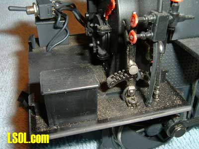 The engineer and fireman seat boxes will just pop off. They are held in place with a small amount of glue. The Johnson Bar is held in place by a small Phillips head screw, visible in the above picture. On each side of the boiler are metal castings that represent injectors. Remove these injectors. There is plastic piping one each side of the boiler that goes up to the top of the boiler. In the picture the engineer side piping is identified by the two globe valves with red valve wheels. Just cut these off flush with the cab floor. Once the cab floor is clear of all details you are ready for the next step. Following the rather brief detail sheets, study the sheets in order to identify the various parts that make up the cab. 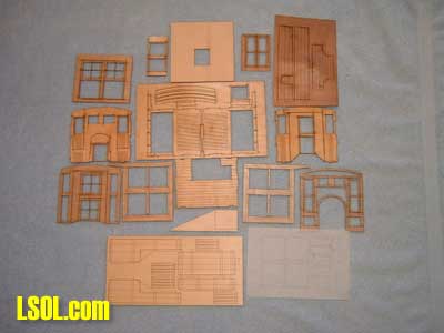 Shown above are the components that make up the cab plus the parts for the tender coal boards. Coal board parts are the sheet in the lower left hand corner. To the right of the coal board parts is a sheet that contains the glazing for cab windows. All of the parts separate easily from the laser cut sheets with no excess to be trimmed or sanded. Recommend that you test fit all the parts before starting assembly.
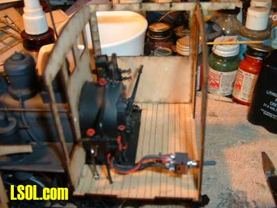
At this point I varied from the recommended construction of the cab. It is intended that the cab be assembled then put in place on the locomotive. I opted to assemble the cab on the locomotive. The reason being that I had installed a DPDT switch with wires running up through the cab floor. Since I did not want to unsolder six wires from the DPDT switch and go through that "drill" again building up the cab on the locomotive was the course of action selected. Assembly follows the same sequence no matter if the cab is assembled off the locomotive or on the locomotive. When installing the cab floor on the engine it is a good idea to have the cab front wall and its thin wood trim applique slid down into the grooves on each side of the boiler. This will help position the floor in the correct location and insure that the front cab wall meets the floor at a right angle. This is only necessary if the cab is being constructed in place on the locomotive. If constructing the cab, as intended, off the locomotive this check is not necessary. The new wood cab floor was attached to the existing floor with SOL-ZAP. In addition to relying on the CA to hold the floor/cab in place I installed a small flat head screw down through the floor just ahead of where the engineer's seat would be installed. On the other side, placing the DPDT switch down through the floor will serve to secure the left side of the cab floor. You may want to use a screw on each side of the cab through the wood floor into the plastic sub-floor just ahead of the seat locations once the cab is installed. 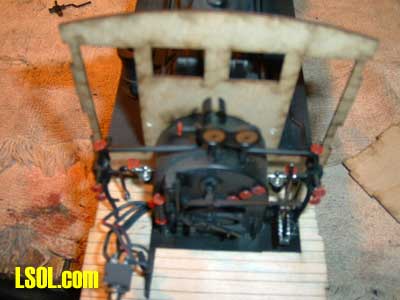 In the above picture the cab floor has been installed along with the front cab wall. At this point I also installed the cab details that had been removed to clear the cab floor. Both injectors and the Johnson Bar have been put in place. The plastic piping on both sides of the cab that go to the turret on top of the boiler were trimmed so they fit tight against the cab floor and secured with a small drop of CA. If constructing the cab off the locomotive the cab interior details will be added after the cab is placed on the locomotive, before the roof rafters and roof are put in place. NOTE: I used Pacer brand SLO-ZAP CA. SLO-ZAP is high viscosity and slow cure. I've used SLO- ZAP over the years when constructing both kit and scratch built wood rolling stock. I have yet to have it fail to hold a bond between pieces. You could also use Titebond III with good results.
 In this photo the front, rear, and one side wall have been installed. The sequence for constructing the cab shell is front wall, rear wall and then the side walls. At this point I decided that the DPDT switch should be installed down through the cab floor so the picture is not accurate as to switch location. 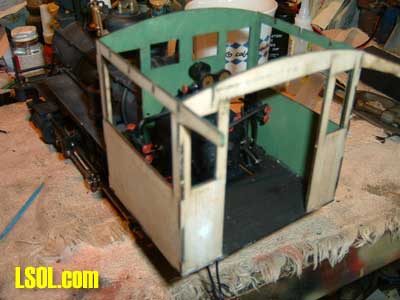 When installing the front and rear cab walls make certain they are at right angles to the floor and square. At this point the side walls will fit in place with no gaps. In the above picture the cab shell has been completed and the interior painted. Plan ahead as to what colors you want for finishing the cab. You'll find it easier to paint cab components before installation. This is particularly the case with cab doors and windows. The next step in the construction is application of the cab trim appliques. Cab trim is applied to front and rear of cab then the side trim is installed. Once the trim is installed the cab corners may be lightly sanded to insure a smooth finish. 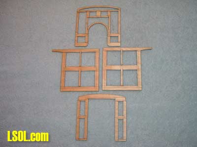 These are the cab trim appliques after removal from their laser cut sheet. Depicted are the cab front, two sides and rear cab wall. 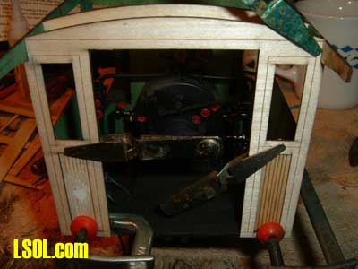
 This is the rear trim panel held in place with clamps while the glue dries. Since the panel appliques are thin it is a good idea to clamp them in place to insure a flat, tight fit to the underlaying wall. 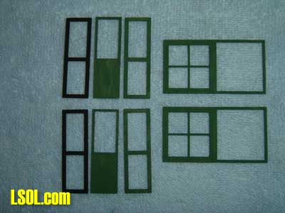 When installing the cab trim test fit each piece before glueing in place. On the side trim check that top, sides, and bottom line up exactly with the cab wall. There should be no overhang on any edge. With this kit the pieces are precision cut so each piece should fit perfectly. Properly aligned there should be no sanding required on any edge in order to obtain exact alignment. When the side trim is glued in place again us clamps to hold the trim tightly to the cab wall until the glue is dry. These are the window and cab door parts. Test fit the windows in the cab window opening prior to glueing in place. The cab door cores should also be checked for fit in the door openings. 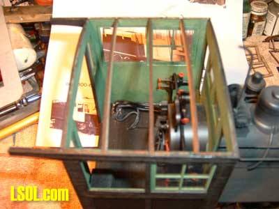 You have the choice of installing the door in either the closed or open position. Each door consists of three parts, door core, outside trim, and inside trim. I recommend that all of these parts be pre painted before assembly. Glazing for the doors should be installed once the inner door panel is glued in place. Once installed then the outer trim is installed to complete the door. Doors should be attached to cab as the last step after the cab has been installed on the locomotive. Side windows are installed and once glue has dried and you are satisfied with the paint then add the window glazing.
If building the cab off the engine, then at this point the cab should be installed. Once installed the cab interior detail is added. This includes the injectors, Johnson Bar, piping from the cab floor to the turret on top of the firebox is glued to the cab floor. You will have to make a seat for the engineer and fireman as the original seats will be too low for the higher cab and window sills. I used 1/2" x 3/4" wood painted black for the seats. Determine length by the engineer figure you are going to use so that the engineer sets at the window opening properly. 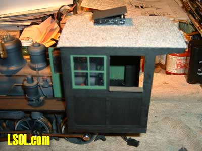 Once interior detail and crew seats have been installed along with side window glazing the three roof ribs are glued and installed as shown in the picture above. At this point you are ready to install the roof. 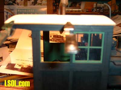 Run a bead of glue along the top edge of the cab walls. Place roof in place and align so the front and side overhang are equal. Hold roof in place with a series of clamps until the glue dries. After the roof is in place and glue has dried the roof vent supports are glued in place and roof vent added. The above picture shows the roof vent in place. Use a small piece of scrap wood to fashion a roof vent support. Glue this centered along the rear of the vent supports and up against the back of the roof vent for support. Note that in the above picture I have applied finish to the roof. In this case I used a textured paint that has somewhat of a sand finish. This coating will be air brush painted later. With the roof in place, cab vent completed, and roof with it first coat of paint the cab doors may now be installed.
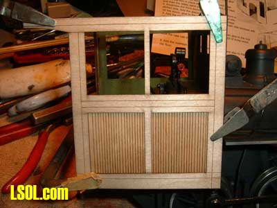
Also the cab window arm rests are now glued in place. I opted to leave the arm rests a natural finish as they appear in the above picture. At this point the cab is complete. There is one last task to complete the locomotive. The Banta kit includes thin wood overlays for the boiler running boards. The overlays provided are an improvement over the plastic wood grained running boards. 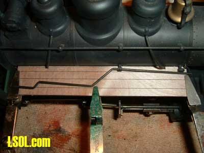 These running board appliques are optional but I thought they looked better than the plastic. Once installed the running boards were painted black to match the engine. 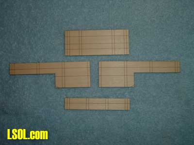 The next step in the conversion process is to construct the coal board extensions. These extensions raise the height of the coal bunker. These are the main parts that make up the coal board. At top is the front of the coal board enclosure. The two long pieces are the sides and the bottom piece is the rear of the enclosure. 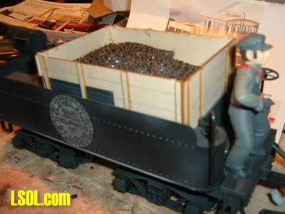 This is the completed coal board extension prior to painting. No modification to the existing tender components is necessary. The only change to be made is removal of the tool boxes that set just to the rear of the water legs. These tool boxes snap in place so they are easy to pry from the tender. I took one of the tool boxes, modified the bottom, and installed it on the locomotive's front pilot deck. It makes a nice addition to the locomotive.
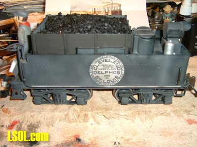 This picture shows the completed, painted coal board extension with a new coal load added right over the existing coal load. For the coal load I used Horticultural Charcoal. This charcoal has a random size more like mine run coal. I premix the charcoal with water and white glue in an old mixing bowl and then place and shape it in the tender. Using this method the charcoal is all evenly coated with the glue/water mixture and will dry as one solid mass. This method helps eliminate a lot of the water/glue mixture that drains down through the load. 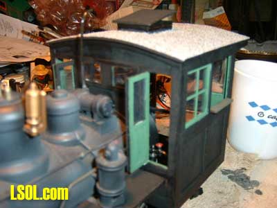 This is the completed cab ready for the roof to be painted and the cab weathered. I used Floquil to paint the cab, running board appliques, and coal boards. 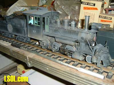 Project completed with Indy on a storage table ready to venture forth on the mainline after a little more weathering. 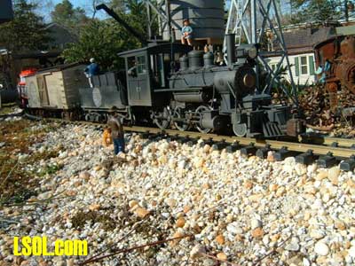
Indy on the mainline at Delphos tank. She's now ready to continue her duties on the CD&StL RY. Bar Johnson, Senior Engineer is most happy with the large cab that better accommodates his ever increasing girth. Try constructing a kit, either locomotive cab or one of the simpler rolling stock offerings. You'll find the project to be fun, educational, and end up with a nice addition to your roster. Top of Page
|


