Scratch & Bash
:
Engines / Rolling Stock
Building a Rotary Snow Plow
Jan 24, 2006


By John Pedersen |
Author
Bio
had seen a USA rotary plow several years ago and thought it was a neat car, but when I found out it was not really meant to blow snow, I kind of lost interest in it.
|
I had seen a USA rotary plow several years ago and thought it was a neat car, but when I found out it was not really meant to blow snow, I kind of lost interest in it. I never lost interest in the idea and like the Mallet I built, it was always some where in the back of my mind that I wanted one that worked. So I guessed I would have to build my own, and after 2 Mallet�s, I felt up to the challenge. First was to figure out what to use for a drive motor, and knowing that vibration will kill any moving parts, what was I going to use as a bearing to avoid vibration. In the 1:1 world, vibration will cause what ever is moving to self destruct, and it will do that faster in a smaller scale like 1:24 or 1:20.3. I save all kinds of parts, some of my favorites come from VCR�s. The cover is great flat plastic for scratch building. They have some nice small motors and gears, and a supply of polished metal shafts. The video head is a marvel of smooth turning ball bearing parts that should have some use. The Drive Unit To the parts box and looking over the goodies, mostly motors for the drive, when I got to thinking this old battery drill should work, and using the chuck it would hold the shaft with no slippage and no couplings to worry about. I cut the handle down to bare minimum, so there was just enough to hold all the workings together. I flattened the one side on a belt sander and put off to one side. 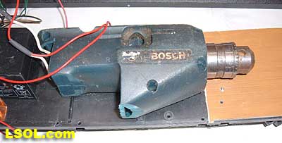 Drill Drive Drill Drive I was going to use a boxcar to put it in but did not want to cut one up in case this didn�t work, so I used an old Bachmann combine car kit that I wasn�t concerned about destroying. I took it apart and removed the insides, but cut the floor where the baggage doors slide in so they would still operate and so I could access the drill chuck. If you have never taken one of these cars apart you probably don�t know just how flimsy they are.
I put the drill in and the floor sagged an inch, and that was with out a battery! The saving grace is that the floor screws to the body with several screws on each side along it�s length so when put together it holds up just fine. The only real modification to the car was to cut off the end steps on one end, and put a small piece of plastic in the body to support the floor from going up into the body at that end. If you use some other kind of car you will have to figure some of those things for yourself. This is mainly a guide as to how I built mine, so if you are tackling this project you most likely are not a beginner in kit bashing. 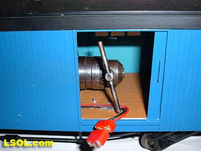 Access to drill chuck and charging plug. Access to drill chuck and charging plug. The Blade Holder Assembly I mentioned the video heads from the VCR as a great bearing, so now how to use them. 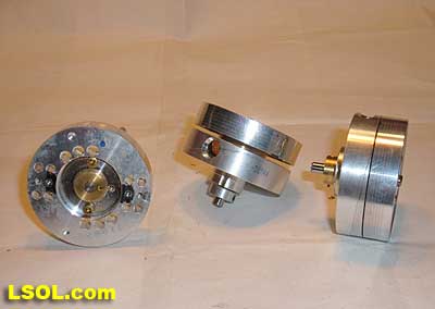 Video Heads Video Heads
With the drill in place I figured out how high the bearings needed to be so they lined up with the chuck. I took the head apart and removed all the parts that are in them. There are several coils and assorted carbon things that need to be removed and it may take a bit of time. When you are done you will have 3 or 4 pieces to work with. 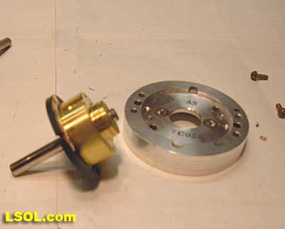 Rotor parts of Video Head Rotor parts of Video Head The small brass center of the rotor will need to be cut down as shown here 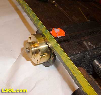 Brass center of rotor Brass center of rotor
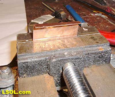
Cut it off with a hacksaw and smooth the back when done. This shaft was far too short for my use, so I needed a longer one. I said there were shafts from the VCR, so I took one out and checked the size. I hammered the short shaft out and put the long one in place. There is a scant difference in size so the new shaft was not as tight as fit as the old one. I drilled a hole thru the center piece and the shaft and used a brass brad as a pin to hold the shaft from turning. 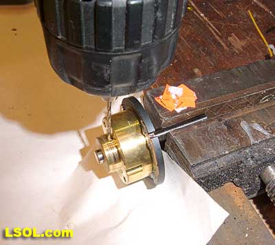 Drilling the shaft for a lock pin Drilling the shaft for a lock pin Where I drilled the hole will be covered by the aluminum back plate, so the pin can�t fall out. Next I tapped the back plate for a couple of 6-32 screws to hold the blade that will throw the snow, I hope. 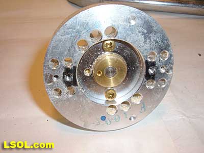 Back plate with holes that I tapped for screws ( in Black) The holes were already there. Back plate with holes that I tapped for screws ( in Black) The holes were already there.
Now put the assembly back together. 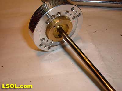 Completed blade holder assembly Completed blade holder assembly The Bearings The other half of the video head has 2 ball bearings spaced apart so it will hold the shaft and turn with no vibrations. 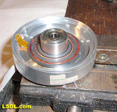 Front bearing assembly, with parts inside before removing them. Front bearing assembly, with parts inside before removing them. After determining the bearing height need I cut the aluminum back plate as shown here. 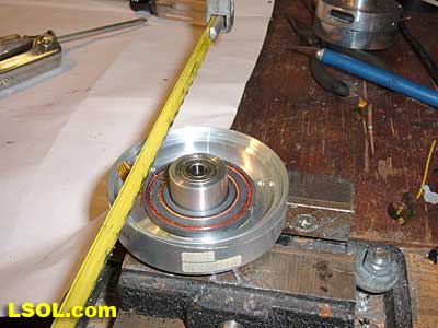 Cutting the bearing to proper height. Cutting the bearing to proper height.
After cutting the bearing I again tapped a couple of the holes in the plate to use as a mount. I used a couple of pieces of copper as brackets and mounted to car floor. 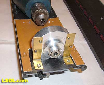 Front bearings mounted to car floor. Front bearings mounted to car floor. The Blade Now to tackle the part that does the work, the blade to throw the snow. The first blade I made was very simple with 8 flat pieces. I had no idea how it would work and was waiting for some snow to try it, but Mother Nature was not cooperating. 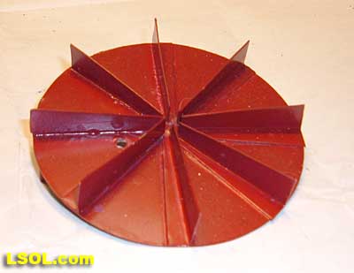 First blade front view. First blade front view. 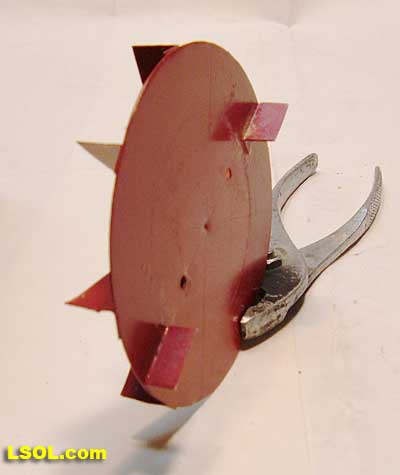 Side view of blade. Side view of blade. I had contacted Marty Cozad after seeing his video and piece in GR. He sent me a couple of pictures of his and said he tested his with sawdust. How simple an idea, and I have no shortage of the stuff. So to the garage and try it out, it seemed to work fine. When we had about 3 inches of snow I tried it and it moved it off the track just fine. A week or so later we had 7 inches of nice powder, but I couldn�t do anything till 24 hours after the snowfall. By then the snow had a slightly hard crust on top, but I figured it would be no problem.
I started the plow and it was like running into a brick wall. It just stopped dead. The blade was not right for the job, back to the drawing board. I knew the next blade needed a bend to dig into the snow and also act like a fan to help blow the snow. The blade would also need to be just a hair in front of the housing so it could break up the snow before it went into the housing. Here is how I made the second blade, and it really works good. 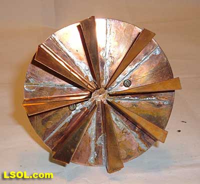 Front view of blade. Front view of blade. 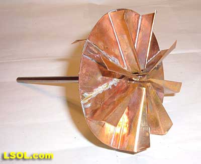 Side view of blade. Side view of blade. The new blade is made of 8 individual parts soldered to the back plate and bent to form a blade that will cut into snow, and act like a fan to help blow it away. I will demonstrate how I built it using cardboard because it would be hard to see the markings on the copper sheet I used. I determined that the blade should be about 4 inches in diameter, so I marked out the sheet in a square. This is the easiest way to make the divisions for the blades that will be mounted to the back plate, and mark the mounting screw holes. First layout the square and draw lines across the square from corner to corner to find the center. 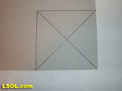 Basic square with marked center. Basic square with marked center.
Next divide the square again along the sides as shown here now divide it in one more place that will be the line that the mounting screw holes will be drilled 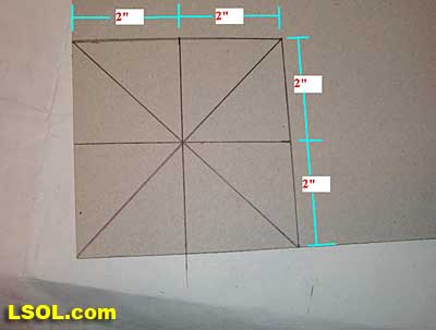 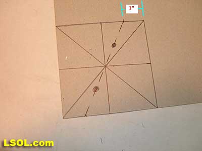 Line for screw holes (black dots) Line for screw holes (black dots) Now use a compass to mark the circle and cut it out, then drill the screw holes, and set it off to the side. Now let�s make the individual blades, I used copper for all the parts but you can use any material you like and can work with. The small blades are 1 3/4� long with a flange bent that will be soldered to the back plate. When finished they look like this 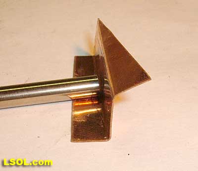 I marked out the blades as follows. 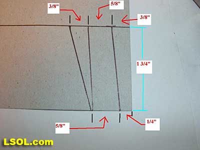 Blade dimensions. Blade dimensions.
Cut out 8 of these and using a vise or something that can clamp the pieces tight so you can form sharp corners. 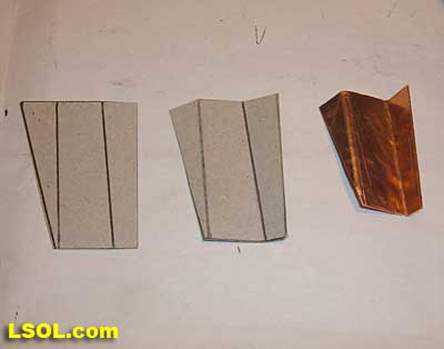 When you go to bend them you need to figure out which way they will rotate so they form a fan. 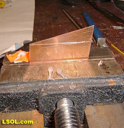 First Bend. First Bend. 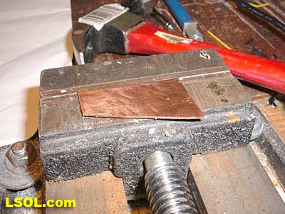 Bend completed. Bend completed. After this bend you need to trim the end square as when they are cut out as shown the top is not square to the flange that will be soldered to the back plate 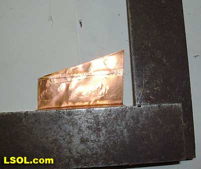 As you can see here the blade is not square, so it needs to be trimmed. It can be done now or later it really doesn�t matter. I needed to trim mine twice, the last time at the very end of construction.
 Third bend. Third bend. When making the third bend, bend the blade about 45 degrees, not 90. When you have them all done and trimmed it will be time to solder them to the back plate. I used a small Butane torch to solder the vanes on the plate. I used an alligator clip to hold them in place, and soldered them on one at a time. By using a small torch there was enough heat to solder with but not to melt the solder on the previously soldered vanes. The copper will dissipate a lot of heat so this was not as hard as I thought it could get. I put the back plate on a vise with lots of open space under it and held the vanes as shown. 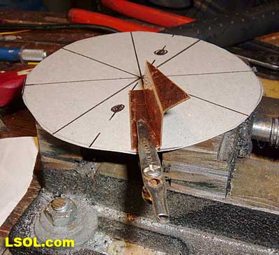 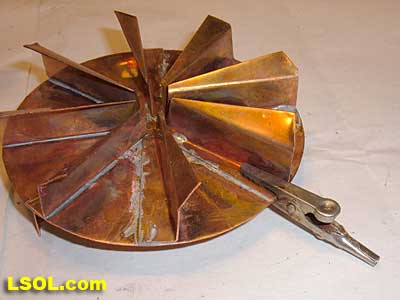 Actual blade. Actual blade. I added 2 small vanes on the back of the blade to help prevent snow from building up behind it when running. I don�t know if it is needed, but I think it is a good idea. Now mount the blade to the rotor assembly. 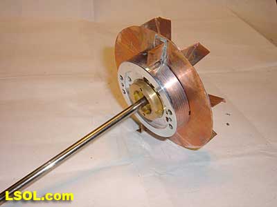 Completed blade assembly. Completed blade assembly.
I made the housing about 1/4 inch larger than the blade. I have used cardboard to demonstrate how I built it. I marked the out line as shown here. 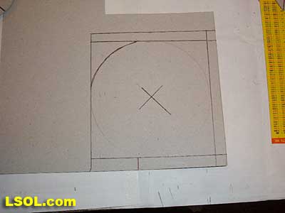 Basic layout. Basic layout. 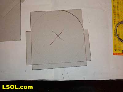 Step 2 Cut Out Step 2 Cut Out 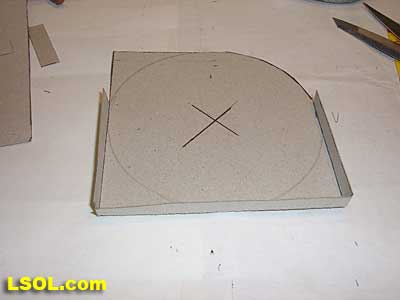 Final cut and fold. Final cut and fold. The side frames were made 1 1/4� wide and formed to fit on the inside of the folds. If I make another I probably would cut it on the outside of the folds and use small screws to hold it while soldering it together. After it was done I would file off the screw heads. 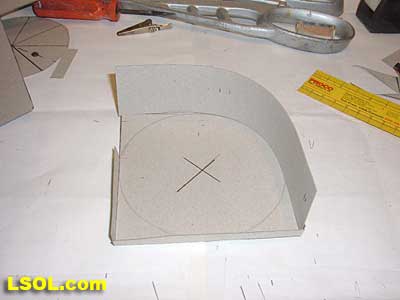 First piece of sides. First piece of sides.
When this one is done add the other side which will be shorter, and then a piece for the bottom. It will appear to be something like this, or could be your own design. 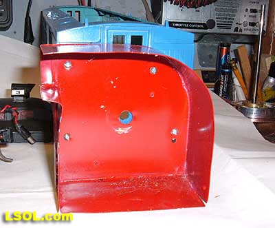 Finished housing. Finished housing. I then marked out when the center of the hole for the shaft will be and drilled the end of the car. I used nuts and bolts to mount the housing to the body, I did not want it to come loose so I avoided sheet metal screws. This housing discharges horizontally, but you could make the chute angle up for greater throw away from the track. The Battery and Controls I mounted the drill then installed an on-off switch through the car floor as shown. 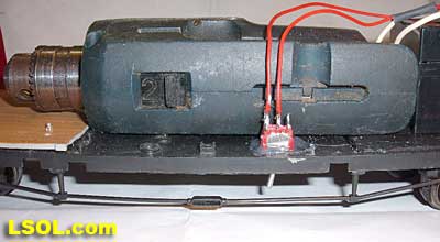 Power switch. Power switch. Next I mounted a 12 volt battery in behind the drill and made a clamp of spare copper strap. 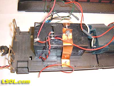 Battery holder and relay mounted on battery. Battery holder and relay mounted on battery. I run track power with a Crest Train Engineer so I can plow from indoors, so I wanted some kind of remote starter in the car. I mounted a 5 volt relay on top of the battery and wired the contacts in parallel with the on-off switch. The coil terminals are connected to a power plug that plugs into the front of the driving locomotive. When the train starts moving it waits a few seconds till the track power reaches 5 volts and the real turns on the drill and it starts blowing snow without my having to do it manually. Yes I am sort of lazy, but love automatic operation. 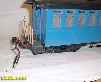 Power plug to control relay and drill. Power plug to control relay and drill. I was now ready to put the body back on, but not the roof. I removed the screws holding the roof on and put the body on I then realized I could see the workings through the windows and knew that would no do. So I took sandpaper and lightly sanded the windows to give that �frosted� look.
Now I was ready to put the body on and screw it in place. Then I put the rotor thru the hole and tightened the chuck and was ready to test again. It was then that I discovered that the car was too high off the rails and would not clean well enough to use that way. I removed the standard wheel sets and installed some small metal wheel sets I had for the small Bachmann mining cars, and the height was just right to clear the track and turnout frogs. It worked very well and I knew it was a keeper, but that battery had a life of only about 10 minutes run time. I checked the running amps of the drill to find out it was a true power hog almost 2 Amps with no load. I had another 12 volt battery that is slim and longer and it fit on top of the other battery and the drill itself. So I wired it in and it is held in place with packing tape across the top of the car body. I now have 45 minutes to an hour of run before I need to bring it in to recharge. 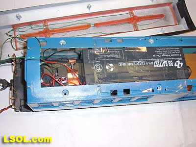 Second 12 Volt Battery Second 12 Volt Battery When it was time to put the roof on I had to drill holes in the side of the roof and put screws into the car side to hold it on. 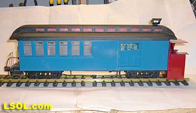 Finished plow. Finished plow. The JFF-NSI Railroad now has a compete roster of snow removal equipment to hopefully meet any snow conditions that Mother Nature would care to send this way. The primary removal system is now this rotary, that is on constant standby in the trackside storage shed ready at any time of day or night to go to work keeping the mainline clear of snow, and the engineer in a nice warm place to watch the crew work. 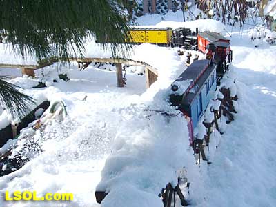 So as the saying goes, Let It Snow!!! So as the saying goes, Let It Snow!!! I hope this helps some one tackle this project, it is not difficult, and not too time consuming. I had a lot of fun making it and I know running it will be even better. If any one has a questions or needs help as always feel free to contact me. Happy Railroading,
John B Pedersen, President and Chief engineer JFF-NSI Railroad
| Did you have a video of this plow in action? |
| John, I thought that there was a video of this beauty in action, back when you first published the article, but I can't seem to find it. Do you have some video footage? Thanks, Bill Kohler Chief Engineer Greenbrier, Cheat & Elk RR You're never to old to enjoy a happy childhood! |
| Bill Kohler - 01/06/2010 - 08:50 |
Top of Page
|


