Scratch & Bash
:
Engines / Rolling Stock
Bachmann Passenger Car Coupler Modification
Jul 16, 2008


By Jon D. Miller
LSOL.com Reviews Editor |
Author
Bio
Jackson & Sharp coaches marketed by Bachmann offer good value along with acceptable prototypical detail for operators of narrow gauge equipment.
|
Jackson & Sharp coaches marketed by Bachmann offer good value along with acceptable prototypical detail for operators of narrow gauge equipment. For me the biggest knock on these cars is the overly wide space between the coaches when coupled. A more prototypical look is possible by a simple modification to the trucks and couplers. Once accomplished, passengers will no longer have to be Olympic class broad jumpers to get from coach to coach. As built the coaches have couplers that extend way beyond the cars’ end beams. No doubt this configuration is made necessary in order for coaches to negotiate tight radius curves such as the two foot radius track provided with Bachmann sets. For those that operate on the larger radius curves of four foot or greater close coupled coaches will operate without problems. 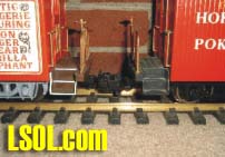 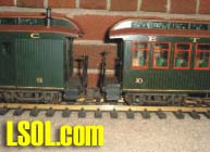 The above pictures provide a comparison of close versus short coupled coaches. Following is the procedure for modifying Bachmann passenger car couplers. 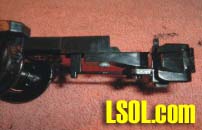 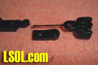 Picture on left above is the unmodified Bachmann coupler. Picture on right depicts the coupler components disassembled into the three major components. Disassembly consists of removing the screw that mounts the coupler to the tongue of the truck frame. The coupler is removed from its short carrier piece by removing the plastic rivet that attaches the coupler to the center piece shown in the above picture. Once the assembly is broken down into its three main pieces modifications are the next step. 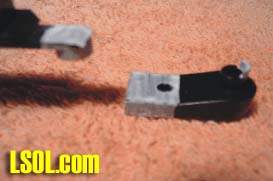
Those portions of the coupler components that are to be removed are marked with white. On the coupler tongue there is a small angled step down. The shank in the right of the picture fits up against this step. First cut made is just in front of this step removing the portion of the tongue marked with white. The distance from the angled step where the cut is made is 3/32 inches. The portion cut from the tongue is 1/4 inch. Since coupler tongues vary slightly make this cut so that the 3/32 inch is maintained. Next the coupler shank piece is cut along the line where the white portion is marked. This cut is made on the flat part just at the line where the coupler shank piece starts to turn up. Also the small half circle tang where the coupler mounts to the shank is removed. That’s the portion marked with white to the right side of the coupler mounting shank as shown above. 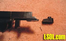 Once the components are cut they should look like those in the above picture. Slightly round the corners of the tongue where the cut was made. Round the corners enough so that the shank will fit tight against the tongue. Place the shank on the coupler tongue with the shank tight against the tongue. Holding the shank in place, drill a hole using a #41 (.096") drill bit down through the shank hole where the coupler will mount and down through the coupler tongue. Next, use a 4-40 self taping screw 5/8 inches long to attach the coupler and shank to the tongue. Place a tight fitting washer on the screw first. Place the coupler on the shank and then place the screw and washer down through the hole in the shank and screw it into the tongue using the hole previously drilled. Tighten the screw so that it holds the washer against the coupler as the washer rests on the shank’s coupler pivot. 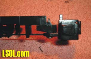 The completed modification should look like that pictured above. You are now finished. What you have is a coupler that will not droop and will be positioned closer to the end beam of the coach. A quick brushing or spray with your favorite coupler color finishes the job. 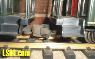 Credit for this modification must be given to Shelton Owens a long time member of Tidewater Big Train Operators and now deceased. Shel came up with this modification back around 1990 or so and passed it on to Tidewater Big Train Club members and that’s where I picked it up. Shel widely distributed this modification to other LS clubs so you may have seen it published in other club news letters in years past.
| Bachmann coaches |
| Nice work around! I've done LOTS of mods to these cars, including replacing the couplers with Kadees, installing LED lights, putting glass in the doors, making "easy remove" roofs, and installing metal wheels. Since Bachmann continually improves the cars, there's always something new to add. Now, if they'd only sell those new metal railings!! Are you listening, Bach-man? |
| Dick Friedman - 07/16/2008 - 09:35 |
| Bachmann coaches |
| Jon, I have converted all my coaches over to A/C couplers. Does this modification work well with the A/C as well? |
| Ron Hill - 07/17/2008 - 18:48 |
| Coupler Modification |
| Ron, I have no idea on doing this modification with A/C couplers. Guess something could be done. Why not experiment to see if you can come up with a mod that will achieve the same result? Dick, I have over 20 B'mann J&S coaches. Most have been modified in some way. All have LED battery power lighting installed. As you no doubt found, LED lights extend 9 volt battery life way beyond that of the original lights. |
| JD Miller - 07/17/2008 - 22:53 |
Top of Page
|


