The following is intended to provide information required for converting a track powered Bachmann 10-Wheeler locomotive to battery power operation. Before starting with the conversion let's take a moment to establish a common terminology for designating the right and left sides of a locomotive. Left and right are designated just like for that of a automobile. Left and right are determined as you face looking forward from the cab. 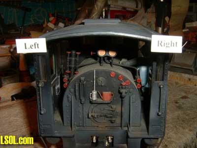
Making this conversion requires a minimum number of tool. You'll need two Phillips screw drivers, one large tip and one very small tip.
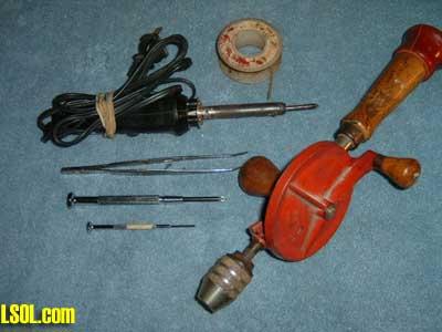
Also, a pair of tweezers, pencil type soldering iron of 15-30 watts, flux, solder, and a small drill of some type. As you work the conversion there will be other hand tools that no doubt will make the job easier. Start with these basic tools and expand with those that help you with the conversion. Add any others that will aid you with the conversion.
The actual changing from track pick up to battery power supply is not all that difficult. What takes the time is the disassembly and reassembly of the locomotive. Also, note that the Bachmann 10-Wheeler is a very basic locomotive with no sophisticated electronics of any type. In fact it doesn't even have a printed circuit board. They just don't get any more basic than the 10-Wheeler. What we are going to do is disconnect/break the path of electricity from the wheels and substitute battery electrical supply. The 10-Wheeler picks up track power through the front and back drivers and the front mounted Pony truck. In all there are eight wheels that pick up power from the rails.
So let's get started. Recommend that all work be accomplished with the locomotive placed on a light colored Turkish towel covering the work area. By using a soft towel dropped screws are not so prone to bounce to the floor and are easier to spot against a light background.
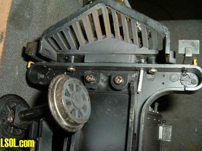
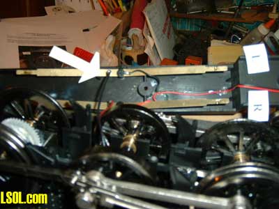
Start with the locomotive in an upright position. The two front pilot to smoke box braces are the first items to be removed. For this you'll need the Phillips screw driver that has the very small tip. There are two very small screws in each bracket, at the pilot deck, that secure the braces to the deck. Be careful removing these screws as they are easily dropped and misplaced.
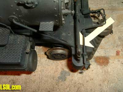
The arrow is pointing to the two screws that secure one of the pilot braces. Once these screws are removed the pilot brace end in the smoke box will slip out.
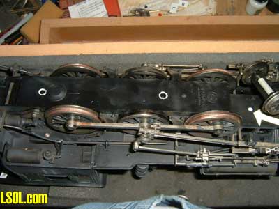
Remove both braces. Now turn the engine over so that it is upside down. It will be necessary to support the locomotive on some type of soft foam or rags so that boiler detail is not damaged and the locomotive will stay in position. I use a Work Station sold by RJJR, Inc. that is designed to support locomotives in a cushioned cradle. You'll notice the 10-Wheeler on the Work Station. These type work stations are not necessary unless you plan to do a significant amount of work on locomotives, then they are very handy to have. 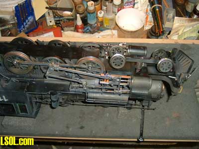
Remove the two Phillips head screws that secure the pilot deck to the main motor cover. This cover extends from the front of the engine to the rear. Once the two pilot deck screws are removed the pilot deck will drop free.
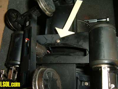
Next remove the screw that secures the front pony truck/cylinder saddle to the locomotive. This is a long thin screw that goes up into the smoke box pedestal. Arrow is pointing to the screw.
Finally, remove the three screws that secure the motor cover to the main part of the chassis. These screw locations are highlighted in white. There is an arrow pointing to the screw at the front portion of this section of the cover. All of these screws have a Phillips head. At this point the bottom cover is no longer held in place by any screws. It can now be removed.
To remove the cover, lift it up at the front near where the pilot deck was secured. While lifting up, hold down on the cylinders. The cylinders stay in place. You will no doubt find this to be a tight fit, especially when taking a 10-Wheeler apart for the first time. Continue to gently lift the cover. At this point a bracket at the back of the cover will have to be freed.
The bracket has what looks like a pipe, on each side, that goes through the bracket. The bracket sets on a slight angle in a slot in the cover. Hold down on the bracket and wiggle the cover free. Again, this will be a tight fit especially on a first tear down.
At this point the bottom cover should be free from the engine. Gently lift the cover up and note there are wires attached to the cover in about the center on each side. There should be enough slack to tip the cover on its side, and clear of the engine. These wires will be disconnected and not used again.
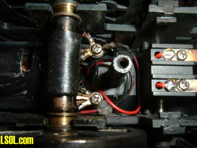
This is what you'll find when the cover is removed. There will be two wires, black on left side, red on right side, attached to the brass contact strips. The arrow is pointing to one of the single pin type plugs that carries power from the wheels into the engine. Just ahead there is a Phillips head screw with wire attached, one on each brass strip. In the picture note that these wires go forward. These are attached to the pony truck.
Unplug the two wires that have the single pin plugs. Cut the wires that are attached with the Phillips head screws. At about the location of the L and R indications cut the wires again to get them out of the way. As the engine is wired for track power the red and black wires with the single pin plugs go forward to a switch on the back of the smoke box front. This switch is a polarity switch. It is not needed for battery operation.
In normal configuration power returns from the polarity switch to the two binding posts just in front of the middle axle. From there power goes to the lights, smoke unit, and motor. At this time don't do anything with the wires that have the little right-angle pins on them. These are the wires that were unplugged from the single pin plugs on the brass strips. Now the wires that will feed power to the locomotive from the batteries/RC receiver will be installed. I use a plug set sold by Aristo-Craft. Most of my locomotives have been converted to this plug set so that my engines and battery cars are standardized. In this way I can use any battery car with any engine. At this point we are going to install a plug set to get power from the tender to the locomotive. You may decide to install your receiver and batteries in the tender, In that case only one plug set is required.
Should you decide to use a battery car (s) then a second plug set will be required. The second plug set will be mounted on the back of the tender to carry power from the battery car, through the tender to the locomotive.
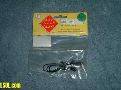
This is a package containing the Aristo-Craft ART 29511. There are any number of plug sets available so pick those that you think will meet your requirements. Do select a plug set that can only be plugged in one way. In other words you can't reverse the wiring by plugging the wires together in the wrong way. These sets, such as the Aristo item, are called polarized plugs.
To continue on, we will now install half of the plug set. I use the female portion of the set going into the locomotive. Male or female the choice is yours. Recommend that whatever way you choose be consistent with all your installations. 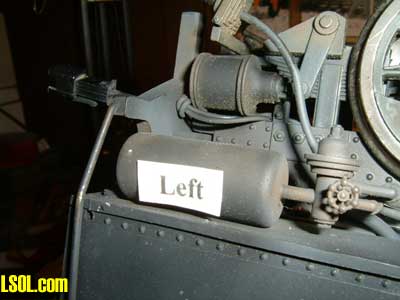
Refer to the above picture. When I started converting to battery power over ten years ago I decided to mount the feed wires left of center on all locomotives, tenders, and battery cars. On the 10-Wheeler, note in the above picture that a hole has been drilled in the rear cab floor brace just above the brake cylinder. The plug wire is feed through this hole, knotted, and then fed through an existing opening in the frame. From the cab brace to the plug end I set the length at one inch.
You can adjust the plug wire coming out of the tender to any length needed to allow for negotiation of curves without putting stress on the plug. Once the plug wire is fed inside the case, route the wire along the case side to a point just ahead of the center axle. This is the point that the wire(s) will be attached to binding posts. It may be necessary to splice additional lengths of wire to the plug set to reach the binding posts; if so, make sure that the splices are covered with heat shrink. Do not use electrical tape on the joints. Tape will get warm/hot, and come loose from the wire causing a possible short circuit.
Next, route the wires to just in front of the middle axle. Allow some additional wire so there is enough to attach to the binding posts and slack so that soldering can be accomplished. 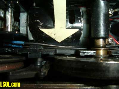
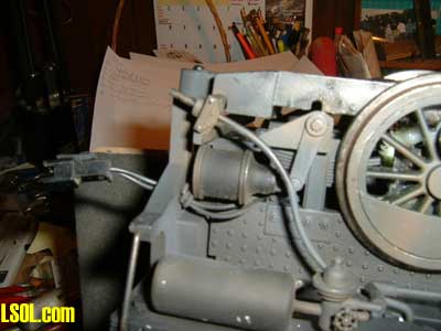
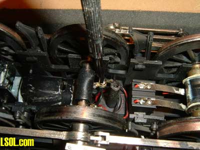
In the above picture you can see the wires running along the side of the case next to the motor. Also notice that to the left you can see blue heat shrink where the wires were spiced in order to reach the binding posts. Once the wires have been attached to the binding posts it would be a good idea to go back and place a dab of hot glue on the wires in the location where the arrow is pointing in the above photo.
The idea here is to fix the wires to the side of the chassis and the motor case. This will keep the wires from shifting and possibly coming in contact with both the rear and center axles. Once the plug wires are routed to the area of the binding posts it's time to make the connections.
Note the two binding posts with the Phillips head screws. It is at this point that the plug wires will be attached. Earlier a wire with a pin plug was unplugged from each brass strip. Cut these wires to remove the pin connectors. Push these wires down into the engine so that they do not come in contact with any metal. There are a number of wires with small brass connectors on their ends that are stacked on the binding posts.
Remove each binding post Phillips head screw, doing one side at a time. Taking the top most ring connector, solder one of the plug wires to this brass ring and reinstall the ring along with the rest of the wires that were attached to that post. It makes no difference what other wire may be soldered to that ring connector.
Once one side is completed and all wires back in position on the binding post proceed to the other binding post and accomplish the same task. At this point the wiring of the locomotive for battery power should be complete. Arrange the wires that are attached to each binding post in such a way that they do not interfere with or touch wires from the other binding post. Just to the front of the binding posts you will notice two metal "fingers" that contact a drum on the front axle. This is the trigger for the chuff of the sound system. In no way is it necessary to disturb these wires or their arrangement.
Make one final check of all wires at each binding post to be sure that none of the wires has broken from its brass attaching ring. This can sometimes happen when working in this area. If a wire breaks loose from its attaching brass ring it will have to be soldered before closing up the case. At this point the conversion is complete.
NOTE: This is a good time to lubricate the gears and motor armature shaft before installing the bottom cover. The bottom cover may now be put back in place. The cover goes back in the exact reverse order that it was removed. It may take a little effort to get the cover back into position. It is important that the bottom case cover fit down tightly to the upper case.
Do not attempt to use the screws that hold the case bottom cover in place to force the cover into position. Trying to use the screws to force the cover into position will only cause the plastic threads to strip out of the stanchions that secure the cover.
Hint: Before replacing screws put a small drop of plastic compatible oil on each screw's threads. This will help to keep the screws from binding as they are installed and also eliminate pulling threads from the plastic stanchions. Now is the time to check your installation by plugging into the plug at the rear of the engine. Using the other half of the plug set make this connection. Then attach the bare ends of the plug set to a power pack. Apply a small amount of power and the locomotive wheels should turn. Reverse polarity on the power pack and the drivers should turn in the opposite direction.
If the motor runs and the wheels turn you have successfully made the conversion. Turn the engine upright and install the front pilot to smoke box braces and their attaching screws. This should be the final step with the locomotive. The next step is to install the other half of the plug wire set on the tender. The plug wire set will be placed through a hole drilled in the front end beam of the tender. 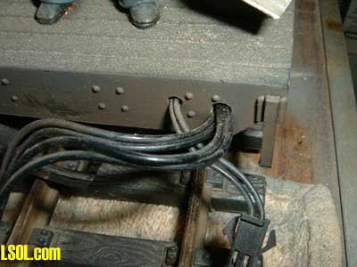
The plug wire is the pair to the inside of the factory installed wires that go into the tender. In the above picture you can see a male plug that will plug into the female plug on the engine. Notice there is slightly more wire exposed coming out of the tender. This extra wire is to allow for the locomotive and tender to negotiate curves without the feed wire being too tight or in an extreme condition pulling the plug apart.
If you are going to install batteries and receiver in the tender then the plug wire should be extended up into the tender to terminate at the output of the receiver. If a following battery/receiver car is to be used then the male plug wire is extended along the bottom of the tender.
At some point it will be necessary to install another plug set, in this case the female end portion, through the rear end beam of the tender. The front wire set and the rear wire set will have to be soldered together and the joints covered with shrink wrap.
Adjust the length of the wires exiting both the front and rear of the tender so that there is a more or less straight run from the front to back of car. Secure the plug wires with hot glue or some other type of glue or adhesive so that the wires under the tender do not interfere with trucks and/or truck wheels. 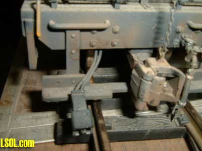
In the example pictured above, I did not drill a hole in the rear end beam. Instead the wire and plug exit under the end beam and the wires are secured under the tender close to the inside of the end beam. In either case the plug wire should be secured so that it stays in place and does not drop down on to the track.
That's about it for converting a Bachmann 10-Wheeler for battery power. Happy Railroading.
| battery conv Bachmann 4-6-0 |
| excelent instructions & photos. |
| david rousseau - 02/10/2011 - 14:07 |
Top of Page