Track & Bridges
You Can Build a Warrren Truss Bridge
Feb 18, 2009


By Noel Widdifield
LSOL.com Managing Editor |
Author
Bio
After finishing the area between Bellefontaine and Muncie on my indoor railroad, I found I needed a second highway bridge to extend the one that Mike Tylick built for me in that area. I spent a few days looking for a truss bridge that would fit into the 30- inch space that I had for the bridge. I found some examples in both books, but not exactly what I had in mind.
|
After finishing the area between Bellefontaine and Muncie on my indoor railroad, I found I needed a second highway bridge to extend the one that Mike Tylick built for me in that area. Mike and Leon Wasiak who are with What-Detail (www.whatdetail.com) had helped me do the scenery on my railroad and were both big fans of bridges. I spent a few days looking for a truss bridge that would fit into the 30- inch space that I had for the bridge. I looked at the book that Mike had sent me, but it was version that had been replaced with several later versions. I purchased the newest version of that book, Bridges and Trestles Handbook by Paul Mallory, and also the Model Railroad Bridges and Trestles from "Model Railroader". I found some examples in both books, but not exactly what I had in mind. 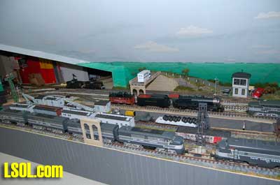 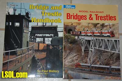 I turned to the Internet and after several days happened to be looking at LSOL.com and saw a bridge that had been designed and constructed by one of our members, Ron Hill. I contacted Ron and asked if he had plans for the bridge. He assured me that he always drew up plans before any of his constructions and offered to send me a pdf of the plan. He emailed me the plan. I downloaded it to my desktop copied it to a thumb drive and took it to my local Kinko's. They enlarged the plan and printed it out full-sized in several views.
I spent a few days looking at these plans and decided that the bridge was too tall for my highway bridge area. I needed a lower version of the bridge and realized that it would require only changes to the heights of a few of the upright vertical girders and a change in the angles to cut for the diagonal front and rear beams. Fastening the full sized plans to the walls of my workshop in my garage in Florida and I was ready to begin. 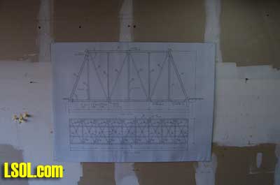 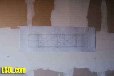 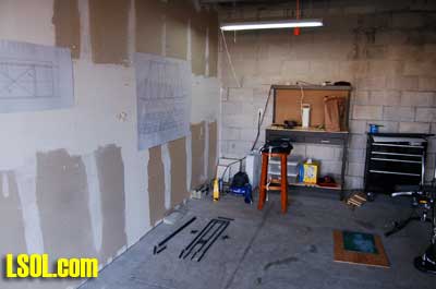
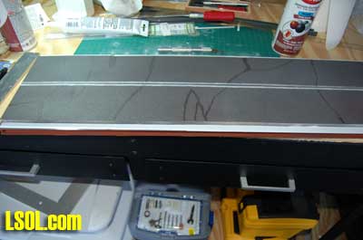
Ron Hill also included a parts list for all of the materials needed in the construction of his bridge and I used that to order the structural material from Plastruct. In this article, I label all of the parts using Ron's terms and placed a number after the part corresponding to the number of the part on Ron's plans and part's list. (Example: floor beams (#4)) The construction material is all ABS and styrene and I used the glue from Plastruct called Plastruct Bondene/Plastic Weld. It "melts" the ABS and/or styrene resulting in a bond that is as strong as the original material. There is one for bonding ABS to ABS or styrene to styrene and one for bonding them to each other. http://www.plastruct.com 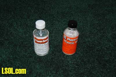 Download Ron's PDF Bridge Plan I began to cut the plastic building materials for the bridge deck starting with the longitudinal floor beams (#4). These required splicing since they were longer than the 24" material available from Plastruct. I found that my Micro Mark chop saw was perfect for this operation and used it to cut all of the beams for the project. 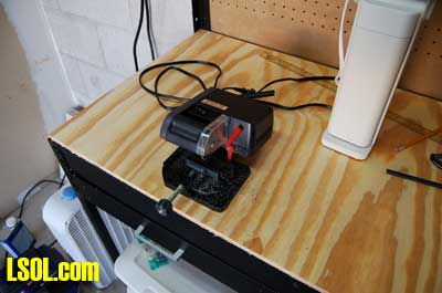 I cut the floor end cross beams (#15), the floor cross braces (#10) and floor stringers (#11) for the deck support after cutting all of the longitudinal floor beams. Laying them out on the floor gave me a chance to be sure everything fit properly and that I had cut everything to the correct length.
I spliced the longitudinal floor beams together using the thin styrene sheet (#16) cut to the proper size. I fastened the end beams to the longitudinal beams and used a square to be sure that everything was correctly aligned. I used the thin styrene sheet end floor plates to strengthen the structure. 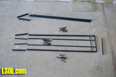 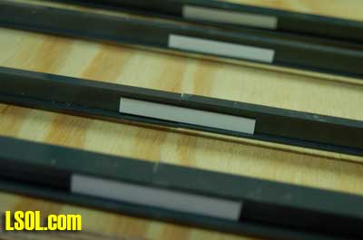 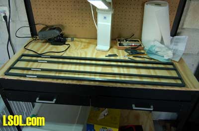
Using the precut floor cross braces and floor stringers, I assembled the deck support and then cut a thin styrene sheet to the correct size with a hobby knife to use as the bridge deck. I laid it in place to be sure it fit. I then placed it aside for later. 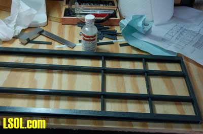 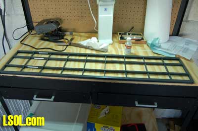 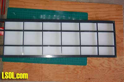 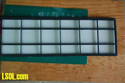
The deck was very strong at this point, but real bridges must be braced with triangular bracing for real strength so I cut bracing plates from thin styrene sheet to fasten the bottom lateral braces (# 1 & #2) for triangular strength. 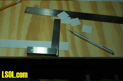 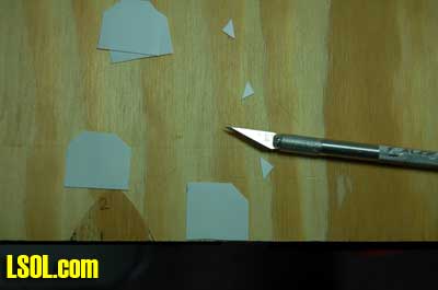 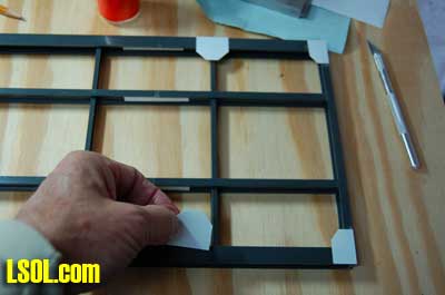 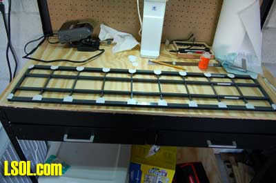
The bottom lateral braces require material that is slightly longer than the 90578 .020 X 10" styrene provided by Plastruct, so I had to cut some short pieces to splice to the 10" strips. Again, I used my chop saw to cut them to the correct length. After splicing them to the 10" strips, I glued them in place between the bracing plates on the bottom of the deck.  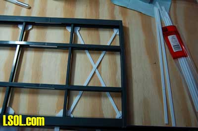 To prepare the deck for painting, I washed the structure in dish detergent and let it dry thoroughly. I used masking tape to protect the top of the longitudinal floor beams, floor cross braces, floor stringers and the floor end cross beams so that I could glue the deck in place after painting the deck support structure. 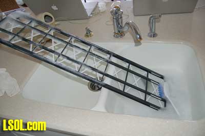 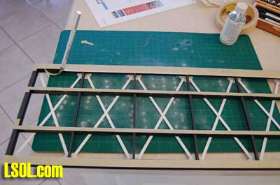
For paint I used Krylon red primer spray paint because it looks very much like the color used for controlling rust on bridges and covers ABS and styrene very nicely. Since I didn't have my spray booth with me in Florida, I constructed one using a brown grocery bag that worked pretty well. Getting complete coverage took some time and I had to hold the structure with rubber gloves while I sprayed it so that I could turn it to get the paint onto all of the parts. The finished product looked pretty realistic. 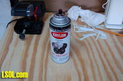 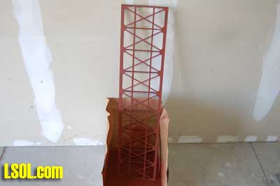 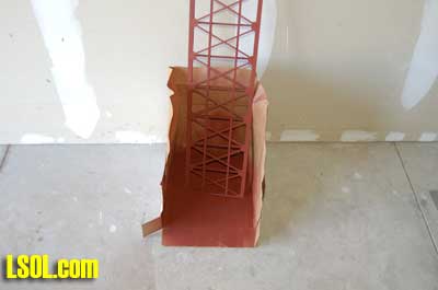
After allowing the paint to dry overnight, I removed the masking tape from the top of the base and then fastened the thin styrene bridge deck to the base. After allowing the glue to dry, I sprayed the bottom of the deck with the Krylon red primer making sure that I didn't get any on the top and that I covered all of the nooks and crannies completely. 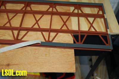 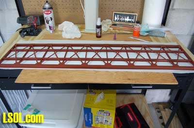 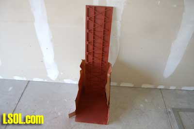 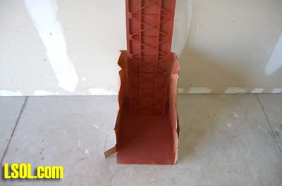 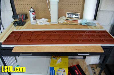
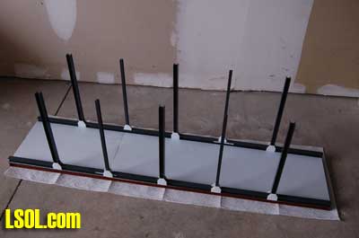
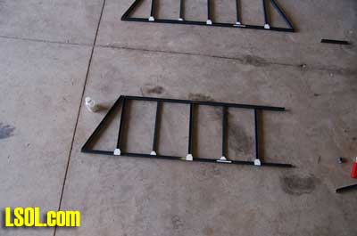
After completing the bridge base, I turned to building the bridge itself by first cutting all of the upright beams (# 7 & 8) to the correct lengths. I used the chop saw to do this making sure that all of the parallel pieces were cut precisely to the same lengths. I then constructed the bracing plates that are used to bolt the bridge pieces together. These were made from the thin styrene sheet that I used to fabricate the bracing plates used for the bridge base. Since these would be visible, I used a pounce wheel to indent the plates so that they would appear to have bolts or rivets fastened through them. 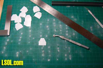 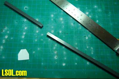 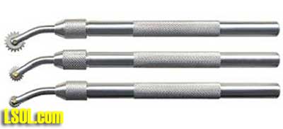
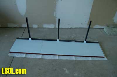
Construction now consisted of assembling the sides of the bridge by starting with the second set of longitudinal floor beams (#13) and fastening the upright vertical beams (7 & 8) to them using the Plastic Weld adhesive. (The #13 floor beams are not labeled on the plans, but are included in the part's list.) I used a square to make sure everything was parallel and square on both bridge sides and used the bracing plates to firm up the beams. Next I fastened the top beams (#5) to the top of the upright vertical beams using Plastic Weld on the plates. 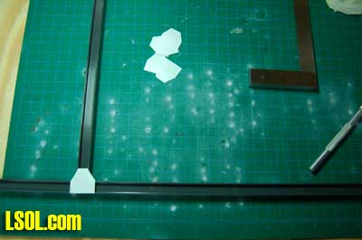 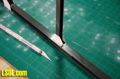 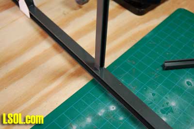 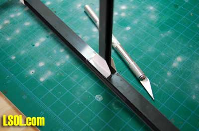
The diagonal front & rear beams (#6) required measuring the angles and cutting them using a razor saw. I found that the chop saw that I had with me in Florida was not large enough to accommodate the size of opening required to cut the beams. The razor saw worked very well. 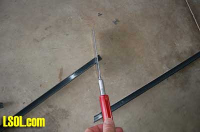 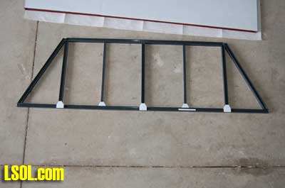 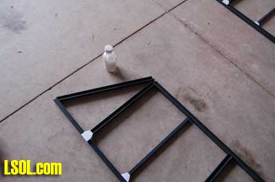
 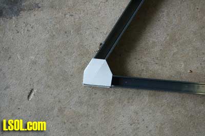  
The bracing plates for the top ends of the bridge beams required a slightly different shape and these were also fashioned from the thin styrene sheet and glued to the top and diagonal front & rear beams. Thin styrene gussets were cut to shape and used to fasten the diagonal front & rear beams to the longitudinal floor beams. Again all of the plates and gussets were indented with the pounce tool to represent rivets or bolt heads. 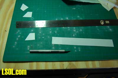 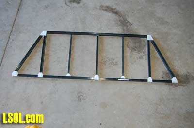 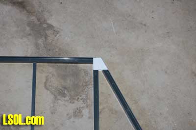 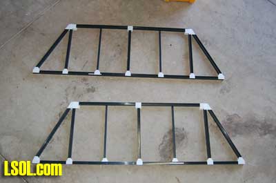
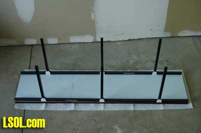
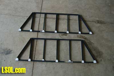
Next I fabricated the side lateral braces (#9) from MS 625 ?? " X .060 stock by splicing the full length piece to the cut piece using Plastic Weld and fastened the beams in place using Plastic Weld and the bracing plates that I had already cut to shape and riveted. 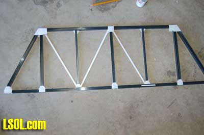 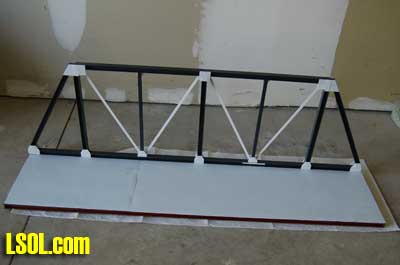 I fit the completed bridge sides in place to be sure they were correctly sized and then glued the top upright crossbeams (#14) in place. 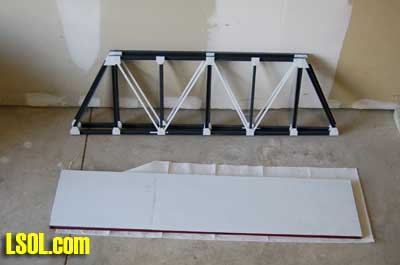 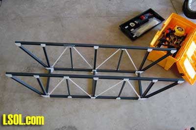
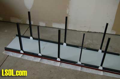
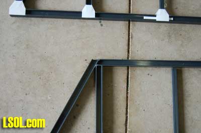
After fashioning the bracing plates for the top of the bridge, I riveted them and glued them to all of the top beam (#5) joints on the top of the bridge. I added the top lateral braces (#3) fastening them with the fabricated styrene plates. I placed the finished bridge onto the deck on top of the deck support structure to be sure that everything fitted correctly. 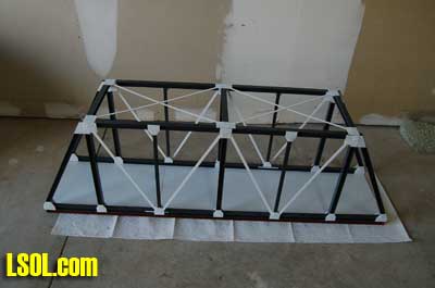 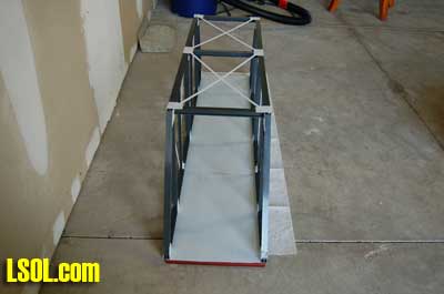 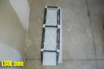
I felt that the bridge needed some additional bracing across the ends, so I cut some one-inch wide pieces of the thin styrene to function as a wide upper brace for the ends. I glued those in place and was satisfied with how they looked and the fact that they added strength to the bridge. 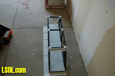 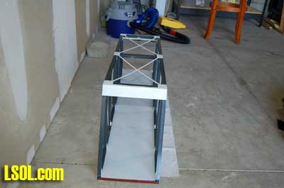 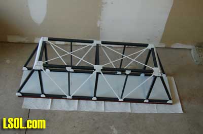
Since my bridge was for a highway, I needed guardrails to go along the inside of the bridge. I used the ??" X ??" I-beams to fabricate the guardrails, spliced them together to reach across the bridge and cut the ends to match the angle of the end bridge beams. I glued them in place at the appropriate height above the future roadbed. 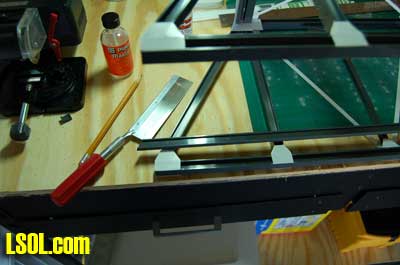 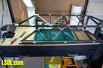 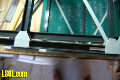 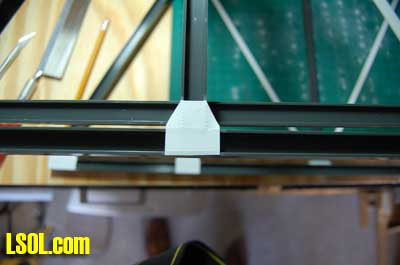
The upper bridge structure was now ready for painting. I masked the bottom of the longitudinal floor beams using masking tape cut to size and moved the structure to my improvised paint booth for painting. 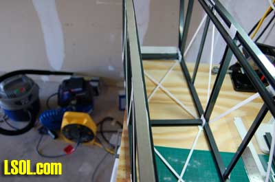 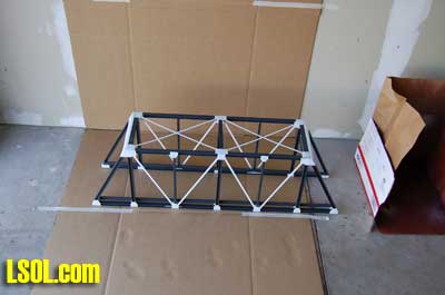 As I prepared to paint the bridge I took a picture of myself to show that I observed the safety precautions that I advocate in my articles. I use safety glasses, a mask to prevent breathing of the paint particles, an apron to keep the paint off of my clothing and rubber gloves. I urge all of you to use these safety precautions when you paint with spray paint. 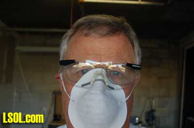
I painted the bridge with Krylon red primer. It took several sessions to be sure that every part of the bridge was covered. 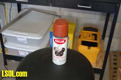 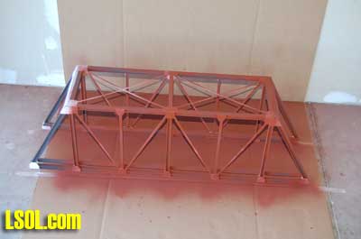 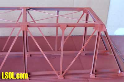 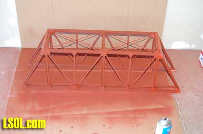
After letting the bridge thoroughly dry overnight, I then painted the bridge using Krylon silver. Two coats of silver were required to fully cover the red primer. 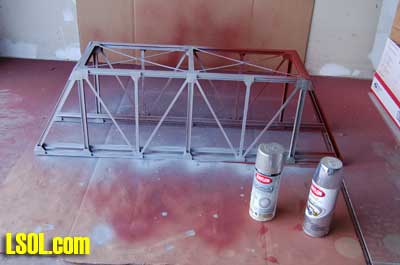 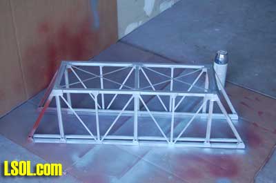 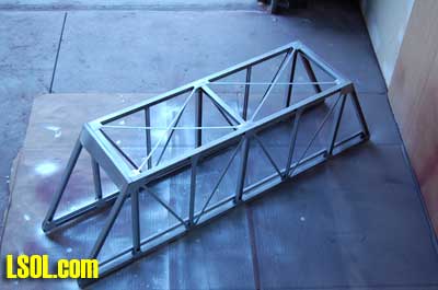 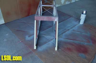
After the paint was completely dry, I removed the masking tape from the longitudinal floor beams and glued the bridge structure to the bridge deck using Plastic Weld and clamps to hold them in place until the Plastic Weld dried. 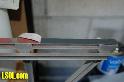 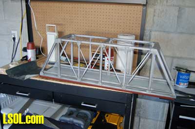 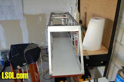 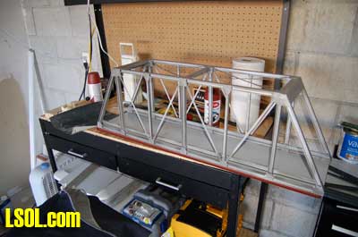 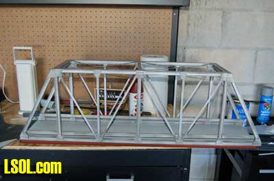
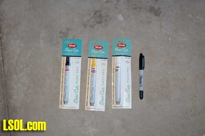
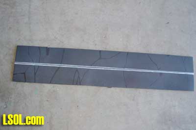
I constructed the asphalt road from a piece of foamcore. I cut it to size and painted it with Rust-Oleum MultiColor Textured spray paint in the flat black color. I used a white Krylon Short Cuts Paint Pen to put the no passing stripes down the center of the roadway and used a black Krylon Short Cuts Paint Pen to draw cracks patched with tar on the roadway. 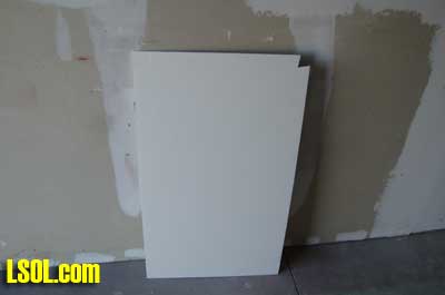 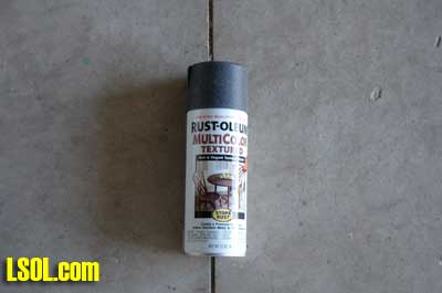 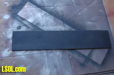
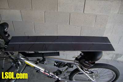   
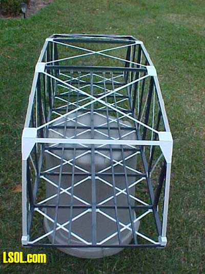
I glued the road to the bridge floor using White Lightening Latex Caulk and allowed it to dry overnight. 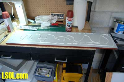 The finished bridge looked pretty good when I moved it outside the next afternoon for photographs. The next step will be to transport the bridge back up north to our Maryland house and install it on my indoor railroad where the bridge pylons wait. I am sure that I will need to do some work on them, because nothing ever fits correctly for me. Everything is measured and constructed to the measurements, but somehow Murphy has a hand in everything I do. 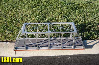 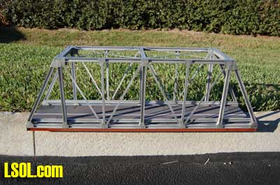 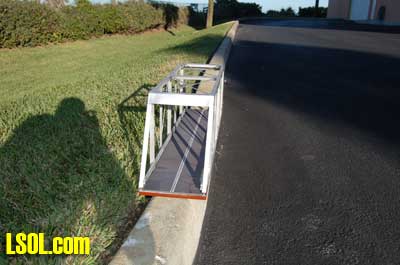
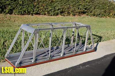 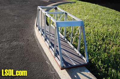 Ron reported that his bridge that was constructed just like this bridge has survived outside for over two years. The only thing that would not last would be the asphalt roadway constructed from the foamcore. The bridge works as a single-track railroad bridge or a two-lane highway bridge. It was a fun project to build and with Ron's bridge plan pdf it is a great project that can be used indoors or outdoors. If you need a bridge you should give this project a try.
| Bridge Project |
| Awesome detail and photos in your article, this will make life easier for the rest of us. what a great project the end result is fantastic. |
| Andrew Wills - 02/18/2009 - 08:30 |
| Bridge Plans |
| Great looking bridge! I,ve always worked with wood but would like to try plastic. Are the Plans & material list available? |
| Richard Tranchina - 02/18/2009 - 09:42 |
| Bridge |
| I have forwarded the plans & parts list to Jon for posting. I am sure he will put them up soon. Thanks, Noel |
| Noel Widdifield - 02/18/2009 - 18:23 |
| Bridge |
| Noel, an excellent article. The bridge really looks good. If I need a highway bridge, I know who to come ask. |
| Ron Hill - 02/18/2009 - 19:19 |
| Bridge |
| Fabulous job on the bridge. You probably invested more time on the photograghs and this amazing article than you did on the bridge. Commendable performance!!! |
| Marcus Kollmann - 02/19/2009 - 07:00 |
| PDF Downloads Parts and Planes |
| I have added links to the Bridge Plans for this Article, Parts List for this Article in the top left of the page |
| Jon DeKeles - 02/19/2009 - 11:50 |
| Bridge |
| Ron, Thank you again for the plans. Marcus, Thanks for the kind words. I always take lots of pictures when I build something. It slows down construction but it sure makes writing the article a lot easier. This was a fun project and hearing feedback always makes us writers feel good about the time and effort we all put in to do the articles. Thanks, Noel |
| Noel Widdifield - 02/20/2009 - 06:55 |
| Truss bridge |
| Great job on this bridge Noel. By the way thank you for the kind compliments on the one I took to the Large Scale Train show last week. Loved my 15 minutes of fame. Like you I used the same books for information and several web sites. The web site below I found very helpful. It has hundreds of photos and many with great close ups of details. http://www.bridgehunter.com/category/railroad/chicago-rock-island-pacific-railroad/ |
| Louis K. Steffenhagen - 03/30/2009 - 09:39 |
| Truss Bridge |
| Louis, Enjoyed meeting you at the show. Looking forward to working with you on the article. Great bridge. Noel |
| Noel Widdifield - 03/31/2009 - 09:13 |
| Plans & Parts list |
| I can't seem to find the link for the Plans and Parts list for the Warren Truss Bridge. Can you please send them to me?? |
| Gerry Keffer - 03/27/2012 - 11:03 |
| Last Input |
| Please disregard my last inquiry for the Plans and Parts list for the Warren Truss Bridge as I did finally find the link. I guess my eyes were just deceiving me... |
| Gerry Keffer - 03/27/2012 - 11:06 |
Top of Page
|


