Track & Bridges
Modular Trestle Construction - Part 2
May 10, 2006


By Andy Chester |
Author
Bio
Having visited a number of garden railroads, I heard some common refrains from several of those who had built trestles. One was keep the trestle out of water or wet soil, for the obvious reasons.
|
Overall Strategy Having visited a number of garden railroads, I heard some common refrains from several of those who had built trestles. One was keep the trestle out of water or wet soil, for the obvious reason of rot. The others were to align the bents with already installed track and to maintain level grade. Those ideas may have been OK if the track was already in place, but that was not an option for me. I had anticipated difficulty with spacing and leveling the bents in the field and in installing girts while crawling around on the ground. So, I wanted to develop a solution that would let me build the trestle in large modular units in the shop, and assemble them in the yard. This would allow for the simplicity of installation of only large components. My roadbed for the non-trestle portion of the railroad was high-density polyethylene (HDPE) in the form of a ladder. Using this material, I built a much larger HDPE ladder system for the trestle. Here are the roadbed ladder (left) and the trestle ladder (right). 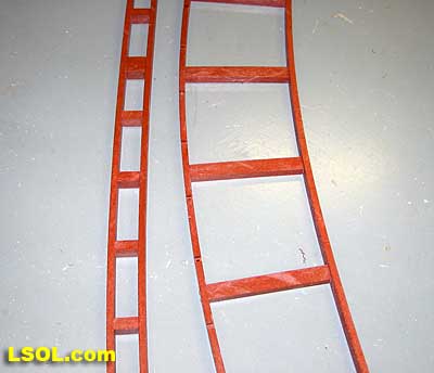 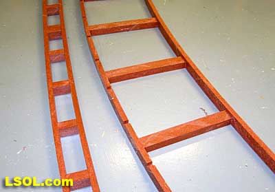 The ladder would provide a stable base, lift the wood bents off the ground, thus protecting them from moisture, and accurately control spacing of the bents. This was accomplished by notching the runners at appropriate intervals to accept the sill beam of the trestle bents.
Building the HDPE ladder for trestle support The HDPE material I purchased was in the form of 1 1/2" X 3 1/2" X 8� boards, nominally 2� X 4�s. I ripped these into pieces 1 1/2" X �� X 8�. As my project is about 25 feet in length, I planned on two 8-foot modular sections and one 9-foot section. In actuality, I cut material for the two 8-foot sections and one 12-foot section to allow some excess should I make a mistake. To allow easy field assembly, I cut rabbets in the ends of the plastic runners to make overlapping splice joints. For each side, I cut a 2-inch long by 1/4-inch deep rabbet in the right end of each section of runner and also from the left ends of the runners. I made sure to execute these cuts on opposite sides of the pieces. Here they are depicted as inside and outside in Figure 1. I used a dado blade in a radial arm saw to remove the material. The HDPE tends to warp after it has been cut so I had to develop some unique hold-downs to keep the material flat in the saw. 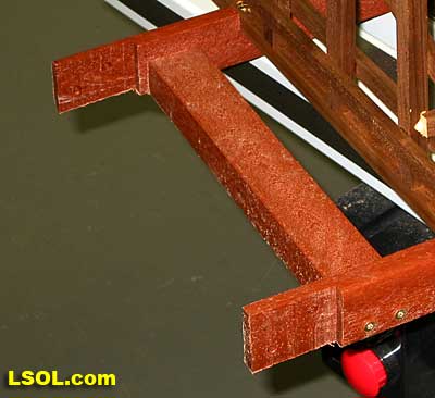 This photo shows a detail shot of the ends of the runners with the lap splices. (Note: If the trestle is to be perfectly straight, then each side of the ladder will be identical. A curved trestle means that each side will be different and they need to be made independently because the radii are different. The next step was to cut notches in the runners of one side of the ladder. I began with the inside runner. The notches were spaced every 6 inches. 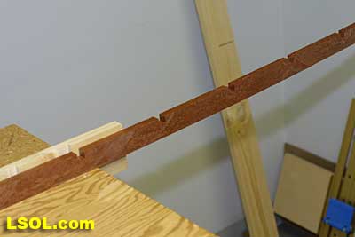 I planned the spacing to avoid notching in the areas of the splices. The notches needed to be 1/2 inch by 1/2 inch to accept the sill beam of the bents. I used the dado blade in my radial arm saw to cut the notches. To make the spacing accurate and reproducible, I did the following: Using a piece of scrap wood as a fence, I cut a 1/2 wide dado through the runner, along with a scrap piece of the runner stock, adjusting the depth so the notch was 1/2 inch deep into the runner. Then I moved the fence exactly 6 inches to the right of that spot and cut a second dado. Clamping the first real runner piece into the saw, I cut the first notch. I located this cut to avoid the splice joints of the runners. I then moved the work piece to the right so that the notch was now aligned with the rightmost dado in the fence. Using a 1/2 X 1/2 inch piece of trestle scrap to act as a key, I fitted it through the fence notch and the runner notch. Every time I cut a new notch, I loosened the clamps, advanced the runner to the right, aligned the previously cut notch with the key and cut the next notch. 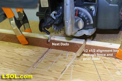
After I cut all the notches in the first runner segments, I had to anticipate the method of attachment of the bents to the ladder. I chose to use brass machine screws. These were placed through holes in the sill beam and screwed into brass-threaded inserts, which were screwed into the base in the plastic runners. There may have been an entirely better way to do this, but I envisioned difficulty in any drilling or screwing during assembly, as the trestle bent structure itself would be in the way. Thus, I drilled holes to accept the brass inserts at the base of each notch. 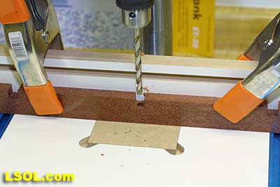 I tried using a jig in my drill press to make this process more accurate, but I found if I controlled the front to back dimension with a fence I could eyeball the side-to-side placement of the bit pretty well using the sidewalls of the notches as reference points. The brass inserts were easily screwed into the plastic but had a tendency to go off the vertical axis a bit. (Note: As I was mocking up the ladder construction for this article, I no longer had any brass inserts. I tried using steel ones, which were more easily inserted and they remained quite straight. Of course, they would rust out of doors. If there were a stainless steel equivalent, it would be ideal.) 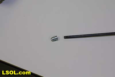 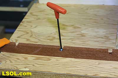
 The next step was to attach the crosspieces or spacers. My spacers were 10 inches long by 1 inch high by 1 1/2 inches wide. The cross section was not critical but these dimensions gave a good target for a couple of screws. With the thickness of the runners at � inch, the 10-inch spacers were made for an 11-inch wide ladder. This accommodated the trestle bents for my railroad, which had a sill beam length of 14 1/2 inches. The ladder width was adjusted depending on the length of the sill beam of the trestle bents. I attached the cross pieces with the wide dimension flat to the work surface. 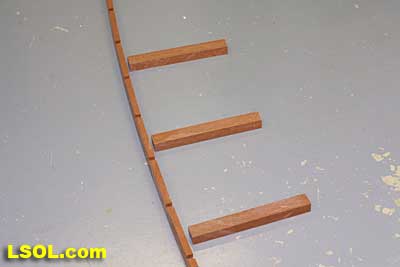 This kept them from interfering with the bent notches. I used a couple of corrosion resistant screws per spacer. Affixing a spacer every foot along the runners, I again laid out the spacers to avoid the areas of a splice. (Note: I clamped a temporary 10 1/2 inch long piece of scrap to the runner and used it to set the intervals between the crosspieces.) 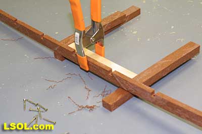
I predrilled the holes for all screws into the HDPE to make assembly easier. One drill for pre-drilling holes and another for screwing made the process go much faster. 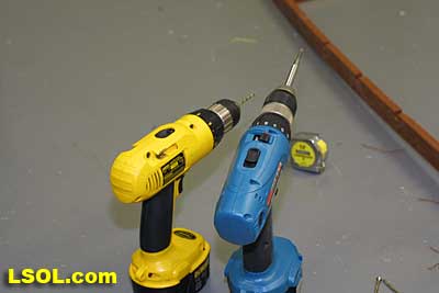 After all the spacers were attached to one runner, I clamped the eight-foot sections together at the lap joints and drilled two �-inch holes through the splice region. I placed them in a diagonal orientation. I used stainless steel bolts (1/4 x 20 x 3/4 inches) lock washers and nuts to join the sections. At this point the ladder had all the rungs but only one sidepiece. 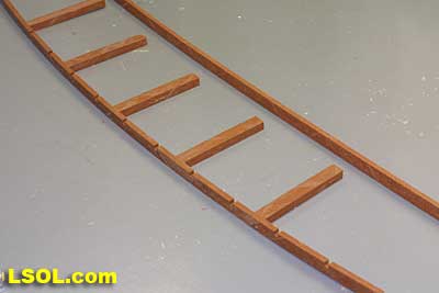 The key here was that the ladder remains quite flexible. I disassembled the 8-foot segments for ease of transport. The segments were taken to the railroad right of way and reassembled. The runner for the opposite side (without notches for bents) needed to be assembled by clamping, drilling and bolting the lap joints together. I laid out the runner with the rungs in the right of way. I built mine longer than necessary so that the ends extended beyond my final length and could be trimmed to fit. It is possible to stake the assembly in place, temporarily, to fit the curves exactly to a plan. I used appropriately sized clamps to clamp across every other crosspiece. 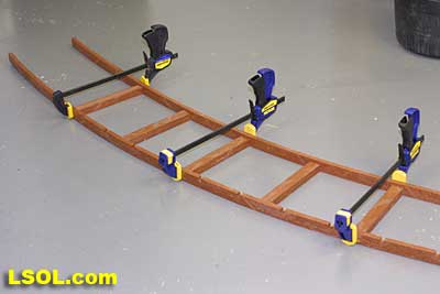 Note the extra length of the smaller radius runner. 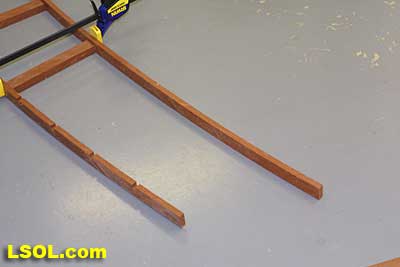
This was why both runners could not be pre-notched � the notches would not line up. The whole assembly felt quite rigid now. I then pre-drilled and screwed the new runner to the crosspieces. Once this was done, I removed the clamps and moved along the ladder, clamping and screwing until the full length was assembled. I finished the intervening rungs once the clamps were removed. 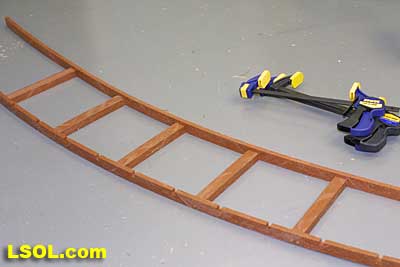 At this point the ladder was close to being finished. But there was one whole runner with no notches to accept the sill beams. Using the first runner as a guide, I inserted a 12 X 1/2 X 1/2 inch piece of stripwood into the notch and used it to mark where the corresponding notch had to be in the opposite runner. 
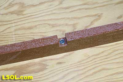
Because of curves, there was no way to easily predict where to put these notches. Thus, I used this empiric method. Once all the marks were in place, the runner assembly had to be removed and the segments unbolted. The runner pieces needed to return to the shop and the appropriate dados cut. Preparation of Bents, Girts and Stringer Beams for Assembly As mentioned previously, I affixed the bents to the HDPE ladder with brass 10 8-32 x 3/4 inch machine screws. All the bents needed to have two holes drilled through the sill beam to accommodate the screws. I carefully measured the distance between the centers of the inserts on the two runners. It was about 10 1/2 inches using the same overall dimensions that I did. Since the sill beam in my example was 14� inches long, I measured in two inches from each end of the sill beam and drilled an oversized hole (1/4 inch) to allow for any misalignment. 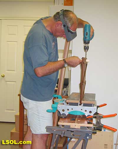 In the picture you can see that I held a block of scrap under the sill beam as I drilled the hole. This was to prevent a lot of breakout of the wood in the sill beam. I did this for all of the bents. The structural integrity of the trestle required longitudinal members to span between the bents and extensive cross bracing. I used 1/4 inch x 1/2 inch cedar strip wood for these components. As with the bents, I cut plenty of wood for these pieces. While I was at it, the stringer beams, which would support the track, were cut. I used three 1/4 inch x 3/4 inch strips for these, laminated into a 3/4 inch x 3/4-inch beam. I had to rip a 1-inch x 6-inch x 8-foot cedar board rather than the thinner fence boards to get the 3/4-inch dimension. Two beams per track were necessary in this design, so I needed 6 linear feet per foot of track and doubled this for a dual mainline trestle. This was a lot of strips. Once I had cut what I thought I needed, it was a good time to apply wood preservative to the long strips. It took me some thought on how to easily treat 8-foot long pieces of strip cedar. I did not have a tray long enough and I only had 4 gallons of preservative to work with. I cut a 10-foot length of 4-inch diameter non-perforated PVC drain tile into two 5-foot pieces. Only one 5-foot segment was necessary. Using PVC cement, I welded a cap onto one end of a five-foot section. I took a generous amount of strip wood and placed it into the pipe. I then took 3-4 gallons of the copper based preservative and carefully filled the pipe to within several inches of the top. The wood floated in this soup, so I had to hold onto it. After several minutes, I pulled the sticks out, turned them over end-for-end and put them back into the pipe. After a similar interval I removed them and let them dry. Using this technique, it is important to protect yourself and surroundings from splashes and drips. I repeated this for as many batches as was necessary to treat all the wood.
Assembly of Trestle Modules Now all the preparatory work paid off, and assembly progressed rather quickly. In the comfort of my shop I attached the bents to the ladders. I used 10-32 x 3/4 inch Phillips head machine screws. I found a small screwdriver that would fit into the space available in the bent and screwed the screws down until the top of the screw was flush with the wood surface.   A module with all bents attached is shown below. 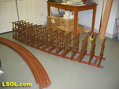
Girts were attached next. They were placed as specified in the diagram from Garden Texture for this style of trestle. I have seen pictures with girts inside and along the outsides of the bents. I put them wherever they fit with the trestle I was modeling. Before I glued each bent, I checked with a small square that it was perpendicular to the work surface. Once aligned, I glued each intersection of the girt and bent. As the modules were eight feet long and the stripwood is 6 feet long, a splice was necessary within sections. I butt spliced them at a bent and made sure adequate glue was used. I left girts longer than the structure at one end to bridge to the end bent of the next module. 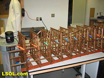 Cheap plastic clamps worked perfectly in tight spaces. 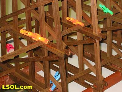
I was able to fit my smallest air driven nailer in between the bents and nailed each joint. Cross-braces were the final component in the indoor assembly. Since my trestle was only two bays high, I chose to cross brace the upper bay. With a three bay high trestle the middle bay might have been more appropriate. I determined the optimum length for the braces and cut plenty of them. I glued and nailed all the braces in one orientation then attached those at right angles. 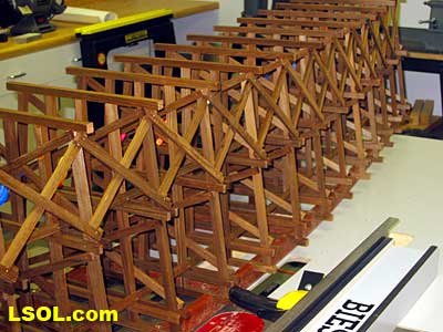 I remembered to make enough pieces to complete the pattern. Several bays could only be braced once the modules were attached in the field. 
Final Assembly It was time to take the trestle outside. Right of way preparation was outside the scope of this article, so I will not cover that part of the job. For the right of way, I used #53 crushed limestone in a trench to provide drainage. 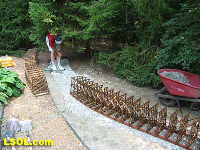 The ease of assembly of the modular concept was realized now, as little further construction was necessary to get the modules assembled. Once the individual modules were connected and cross bracing was completed, the HDPE plastic foundation was covered with gravel to ballast it in place. I filled in about an inch of gravel and will top it later with crusher fines (flume stone here in Indiana) for better scale appearance. It took less than a day to install the trestle to this point. One last tricky part remained. As you can see, my trestle makes a lazy S curve and I somehow had to glue up four stringer beams which conform to this curving contour as well as maintaining proper spacing between the tracks. My spacing was 7 inches on center. The solution I used for this part was to cut small jigs that would sit securely atop every other trestle bent. Clamps were used to ensure the jigs did not slide as the stringer beam strips were positioned into the jigs. The top beam nested in a dadoed groove in the bottom side of the wooden jig. 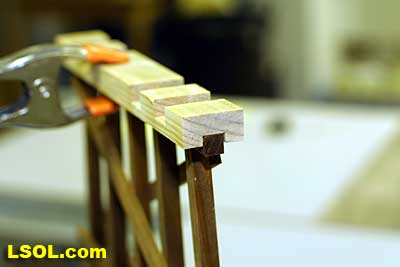
The top surface had 4 notches cut in it to capture the stringer beam. 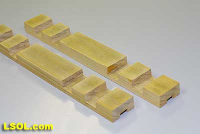 Since the beams had to curve, I laminated them from 3 strips of 1/4 x 3/4 inch stock which when glued up was plenty strong. 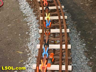
It got pretty sticky at this step. 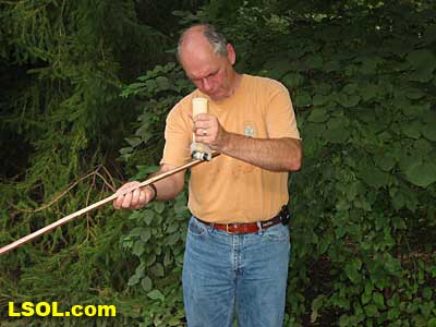 At the end of individual stringer beam pieces, I tried to stagger the butt joints. 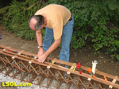
(Here is another view of the process.) 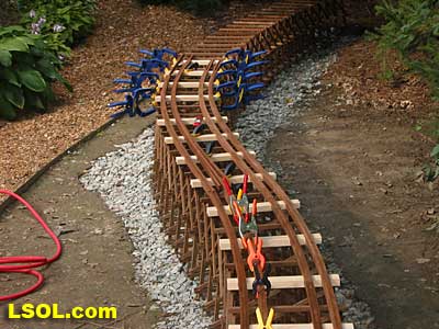 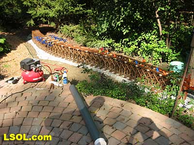 It took about 2-3 days to complete the stringer beams. The limiting factor was the number of clamps I had available. Once the glue dried I removed the jigs and turned them over on the tops of the beams. I captured the stringer beams in the slots and centered them over every other bent just as before. I clamped several of the jigs to the bent underneath to prevent everything from shifting. I then screwed the beams to every other bent (the ones not covered up by a jig). I pre-drilled the holes and countersunk 1 1/4 inch #6 brass woodscrews at every bent. Winter has arrived, and the trestle still awaits track. So far the snow and animals have not damaged it. This spring I will finish the abutments to the trestle and add the track. 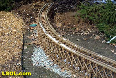
| Trestles |
| Where can I find the materials that you make the wood tretles out of. Do you cut your own out of large pcs? |
| Jeff Schiller - 01/22/2008 - 19:03 |
| See Part 1 |
| Jeff, read part one, page four on how to make scale lumber for trestles. http://www.largescaleonline.com/members/emag/article_539.html?page=4 |
| Rick Henderson - 01/22/2008 - 20:42 |
Top of Page
|


