Background How many hobbies can you blame on your spouse? My wife is an avid gardener and she has toured many beautiful places including the Chicago Botanic Gardens. After her trip there, she encouraged me to go and see the model railroad gardens, designed by Paul Busse, that are a major attraction at the Gardens. After one trip to Chicago, where they are located, I was hooked. I had to build my own backyard railroad empire. Well, perhaps something short of that.
I have always enjoyed building things; woodworking and electrical projects have always filled my shop. A garden railroad seemed to be a natural extension of my interests. That was three years ago!
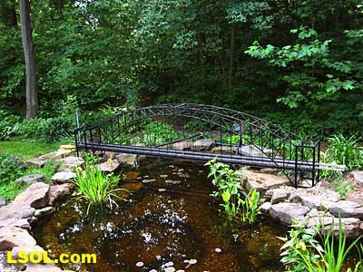
We decided a water feature would be a perfect centerpiece for a garden railroad, so the first summer I dug a pond. We then joined the Indiana Big Train Engineers group to learn more about garden railroading from local train enthusiasts. After several road trips to neighboring garden railroad clubs during the second summer, I was in sensory overload. How could I ever build one of these magnificent pikes?
Although I suffer from the analysis to paralysis syndrome, a year long-study of other railroaders’ efforts helped to diminish my anxiety. This spring I turned the first soil. I had heard enough of family and friends asking, “So when is the railroad going to be done?” when I had not even started.
As a kid, I remember seeing my grandparents off from Chicago to Los Angeles on the gleaming Santa Fe Super Chief. I knew I wanted to create a railroad that could accommodate the long consists of streamlined passenger cars of the 1950’s and a representation of the long unit trains of the current era. The foreground of my railroad had to have some sweeping curves and a bridge over the pond I had already built.
Although not particularly appropriate for this modern era standard gauge road, I loved the look of a long curved trestle. This had to be one of my focal points too. This trestle needed to be 25 feet long, two bays high with support for dual mainline tracks.
I developed a method of trestle construction that allows much of the work to be done in the shop with delivery of 8-foot modules to the worksite for leveling and final installation.
This article is a “how to” guide for building such a trestle. You may want to alter or refine the approach, or you may be stimulated to develop techniques appropriate to your own railroad, I hope this article helps you get started.
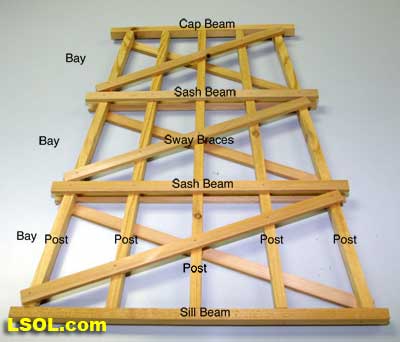
I have listed some terms used in trestles that will help in understanding this article.
Bay – Also called a story. These are the vertical sections of an individual bent.
Bent – Also known as a frame bent when constructed out of square posts. These are vertical structural member of a trestle, which supports the stringer beams. Ties rest on the stringer beams.
Cap Beam – The topmost horizontal member of the trestle bent. It sits atop the posts. Cross Braces – More correctly called "wall braces" these are the crisscrossed braces that connect adjacent bents.
Girt – Horizontal braces that sit atop sash beams or sill beams that connect bents and run the entire length of the trestle.
Post – Also called columns when square. These are the vertical members of the bent, typically 12 x 12 inches.
Sash Beam – Horizontal beams that divide the bent into sections (e.g. bays or stories).
Sill Beam – The bottom most horizontal member of the trestle bent. Generally bolted to a foundation.
Stringer Beam – Heavy beams that sit atop the bents and in real trestles typically span two or more bents. The configuration and size of the stringers is determined by the load rating and distance spanned between bents.
Sway Brace - Angled braces on either side of a bent, attached to posts, cap beams or sill beams, typically one on each side of each bay or story.
Some other terms that are not directly related to trestles, but help understand my construction techniques are listed below.
HDPE – High-density polyethylene, a plastic in this case deriving from recycled milk jugs and the like.
Module – A section of fully constructed trestle with attached HDPE ladder foundation. Several modules are attached to form longer trestles.
Rung – Used interchangeably with crosspiece to indicate the part of the foundation ladder that attaches the two sidepieces or runners.
Runner – Used interchangeably with sidepiece to indicate the long strips forming the sides of the ladder foundation. Also part of the bent cutting sleds, see below.
Sled - In this context, a wooden device that supports a jig for laying up the trestle bents on the top surface and has an attached runner on the bottom surface that fits into the T slot of a table saw. This allows the sled and jig to be pushed past the saw blade for precise and repeatable cutting of trestle bent components. It also keeps hands away from the saw blade.
Part 1 Lumber and Bents Making Scale Lumber
By the looks of many LSOL photos, most members need no instructions on making scale lumber, but I learned a lot from my attempts and have some suggestions.
Redwood is not a reasonable option in Indiana. Cedar, however, is ubiquitous. To minimize waste I used dog-eared cedar fence boards as a source of lumber for my trestles.
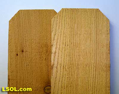
These boards were about 5/8 inches thick rather than the 7/8-inch of a nominal 1 x. I have a small surface planer, which I used to plane these boards to 1/2 inch thickness.
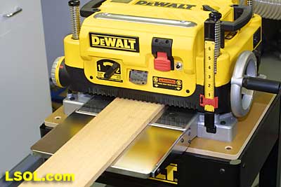
By alternating sides of the boards through the planer, I ended up with pretty good-looking stock. In choosing boards, I avoided as many knots as possible. The stripwood broke, kinked or twisted at the knots. I ripped 1/2 inch and 1/4 inch strips from these boards. Using a feather board and hold downs to keep the wood against the fence and table helped in getting uniform strips.
I probably cut up 20 of the fence boards in three sessions. It was very easy to underestimate the amount of wood needed and the amount of waste generated.
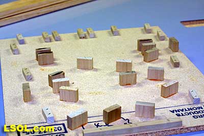
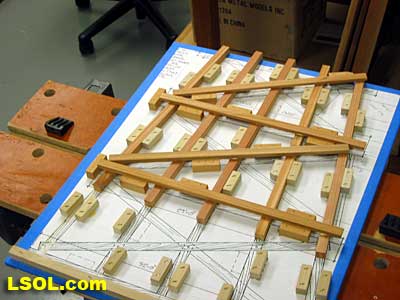
I cut all the stock pieces for all the bents at one time so that assembly would go quickly. A miniature lumberyard quickly developed.
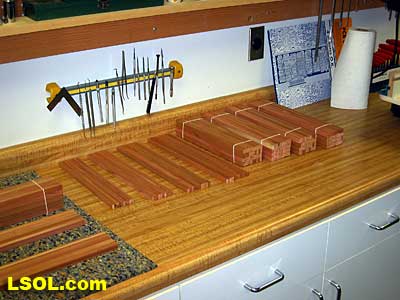
For example, 50 bents require 250 posts, 100 top sway braces, 100 bottom sway braces etc. My wood was very wet so I tied up the cut pieces with string so they would not warp as they dried. I did this with 6-foot strips for the girts with a less satisfactory outcome. There was some twisting with these.
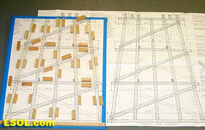
Making the Trestle Bent Jigs I purchased trestle plans and 1:24 scale drawings of bents from Garden Texture. Their dual track design seemed appropriate for my needs. You will need a full size drawing of the bent you are going to build. Make a copy or two in case you damage one in the process of building the jigs.
For those unfamiliar with trestle terminology I have added the basic terms to a photo of a test bent I made.
According to the plans I was using, the bents were spaced 6 inches on center. Thus, a 25-foot trestle needed about 50 bents. I wanted to devise a system to easily make uniform bents. I utilized a series of jigs with two functions. The first function was for laying up, gluing and nailing the bents. For the second function, I used the same jigs as sleds in my table saw to accurately cut off the tops and bottoms of the post beams. This avoided having to measure or even know the exact angle of the cuts.
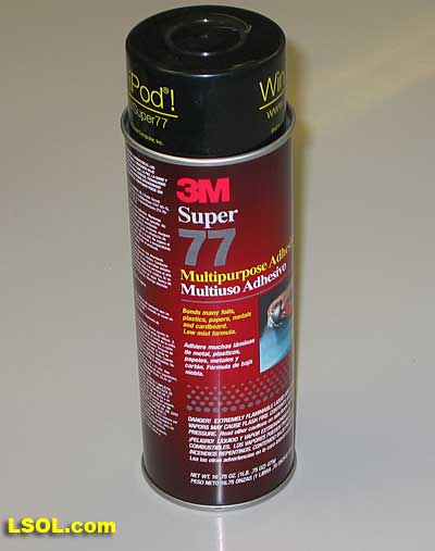
I trimmed my bent drawing so that it was perhaps 1/2 inch larger than the actual bent image. I glued this “blueprint” to a similarly sized and accurately squared piece of 1/2 inch thick particleboard using 3M 77 spray glue, which was applied to both the paper and wood surfaces.
I glued the drawing so that the sill beam upper edge was parallel to the top of the board. I taped all the edges so that the print would not peel off with repeated handling.
The jigs utilized the miter or “T” slot found on most table saws. I attached an appropriately sized (mine required a 3/8 thick by 3/4 wide.) hardwood strip to the underside of the jig with countersunk screws and glue.
The guide strip should move smoothly in the miter slot without excess play. (I planed the guide strip carefully then waxed it with paste wax after attaching it to the board.)
The position of the strip was important. It needed to be parallel to the cap beam and was attached so that the bottom of the cap beam was appropriately spaced from the table saw blade. [Example: My saw’s T slot is exactly 5 1/2 inches from the saw blade.
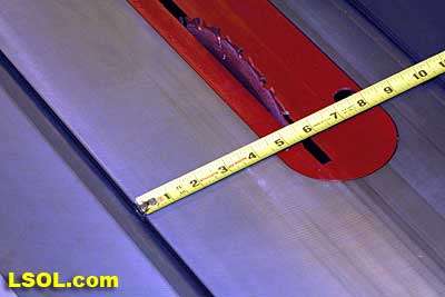
I drew a line on the bottom side of the jig where the bottom of the cap beam was on the front side. 5 1/2 inches below this I drew another line parallel to the first. I then screwed and glued the hardwood strip to the underside of the jig with the blade facing edge of the strip aligned along the pencil line. The first time the jig was pushed through the saw, the drawing of the cap beam and the underlying board was cut off exactly at the junction of the post beams and cap beam.
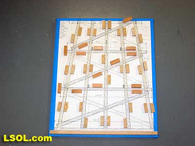
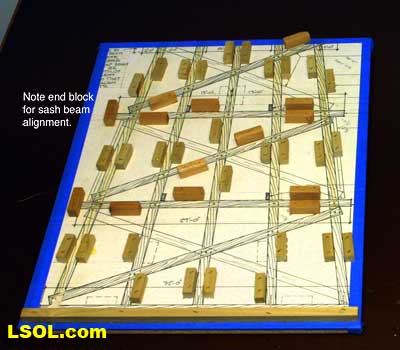
The drawings I purchased had markings for small blocks to hold the bent components in place. I cut multiple 1/2 x 1/2 x 1 inch blocks and used my air nailer with 7/8-inch staples to hold these in place. I installed the blocks for one side of a post, then lay in the post beam and stapled on the blocks for the other side.
I had to put in a real post beam so that the blocks would be the correct distance apart for the timbers. Had I just used the locations indicated on the drawing, they might have been too close together and the posts would not fit at all. I had to be sure that the blocks were not too high so as to interfere with the positioning of sway braces or sash beams. (If the post blocks had been slightly less than 1/2 inch on a side there would have been no interference and the braces would cross right over the blocks.)
After the vertical post blocks were in place, I did the same for the sash beams and sway braces. Since these rested on the face of the posts, the blocks had to be somewhat taller than 1/2 inch. I used 5/8 x ˝ inch cross-section blocks for these. (Note: Some railroad’s sway braces go from upper right to lower left while others chose the opposite pattern. This was the time to pick this orientation.) Once all the blocks were in place it was time to make a transfer pattern.
This was an incomplete bent. I put the posts in place, added a drop of glue where the sash beams and sway braces crossed the posts, and nailed these parts in place.
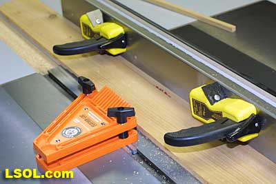
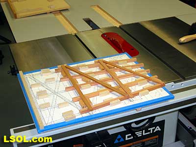
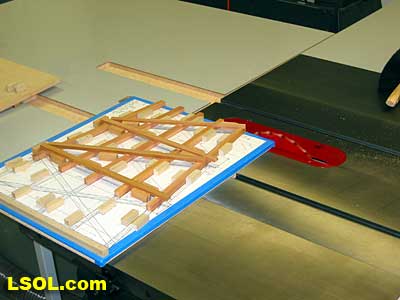
Placing the jig in the miter saw slot, I trimmed off the tops of the posts, (see photos below illustrating this)
Remove the transfer pattern from the jig. Your first jig is done! (Note: in all my photos the blade guard was removed for clarity. The sled allows you to keep your hands well away from the blade, but a guard is still the safest way to protect your fingers. I always use the guard and hearing and eye protection when using the saw and dust collection systems, too.)
The next jig was similar but simpler.
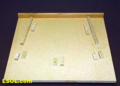
Its function was to allow trimming the bottom of the bent posts in the same fashion I trimmed the tops. The base of the jig was a squared up piece of particleboard slightly larger than the bent I was making. I attached a strip of wood along the top edge of the jig. I placed the top of the transfer pattern against the strip of wood, centered it and lightly clamped the pattern in place. Blocks were attached, as before, to hold the pattern in place. Just a few blocks were necessary.
I then removed the pattern.
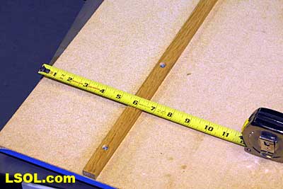
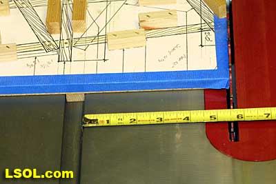
As with the first bent, a hardwood runner was affixed to the underside of the jig to make a sled. Its position determined the height of the finished bent. [Example: If I needed a 25 inch high bent, the posts needed to be 24 inches tall with 1/2 inch added from the cap beam and sill beam. I drew a line on the underside of the jig 24 inches from the top of the particleboard. It had to be parallel with the top as well. I marked the position of the runner. It too had to be parallel to the top of the jig. The blade side of the runner was placed the same distance from the 24-inch line, as the blade side of the miter slot was from the blade (in my case 5 1/2 inches.) Once this was determined, I attached the runner as before. I now passed this jig through the saw to trim it to the desired length.

The second jig was done!
The third jig was the easiest.
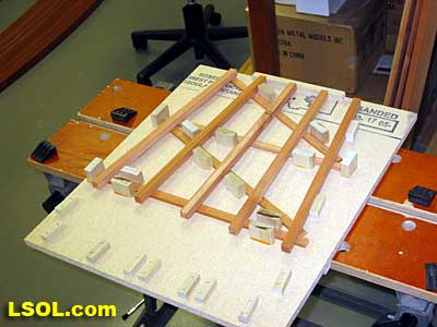
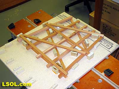
This was used to simplify the glue up of the opposite side of the bent. A scrap piece of particleboard worked as long as one edge was straight and it was as big as the largest bent. Tacking a strip of wood to the top of the jig, I put the transfer pattern against the top strip and centered it. I placed 1-inch tall wooden blocks in appropriate places to align the sash beams with the ones already in place on the opposite side. A block at one end of each of the beam aligned them left to right.
Similar blocks were placed to orient the sway braces appropriately. Since these blocks were so tall, I glued them in place. The goal here was to minimize the variation from bent to bent. I still had to eyeball the location of the sway braces to some extent. Now all the jigs were done. Now came the easy part – making the bents.
Building Bents First, I made sure that all the stripwood pieces were ready for the number of bents I planned to make. To avoid becoming totally bored with the repetitive nature of the project and to allow some sense of completion, I made bents in batches of 10. I laid up the post beams in the first jig. I found that my much used and abused Black and Decker Workmate held jigs perfectly with the sled runner placed loosely between the Workmate jaws. The posts needed to be long enough and positioned so that they overhung the edge of the sled (the top of the bent) and also extended beyond the final length of the posts. (the bottom of the bent) so that they were trimmed to the correct and final length.
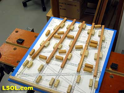
If they were not positioned accurately, one end would not be trimmed and would have ended up being too short. This now appears obvious, but in my haste, I did not pay close enough attention to this on one post and had to tear the bent apart to reposition one post. I dotted a good brand of outdoor glue (e.g. Titebond II) where the sash beams and sway braces crossed the posts. I put the sash beams in place first, against a left sided alignment block and nailed each intersection with a 5/8 brad using the air nailer.
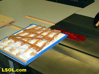
I then placed the sway braces in place pretty much eyeballing their location and nailed them in place. Running the whole jig (sled) through the saw, I trimmed the tops of the posts.
I removed the bent and placed it in the second jig and trimmed the bottom of the posts.
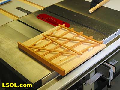
I removed the bent and set it aside. This process was repeated for as many bents as I needed to make.
The beams and braces for the opposite side were attached to the bents using the third jig. These were added in the same fashion to the bents as they were for the first side.
Once all these were attached and the glue had set, the bents were completed by adding the cap beam and sill beam. To assist in aligning these, I put a pencil mark in the center of each of these beams. Then I put a dot of glue on the top (or bottom) of each post and centered the pencil mark on the center post. I nailed the beam with a 7/8 or 1-inch nail (not forgetting to change out the 5/8 nails – they were too short) through the beam into the post.
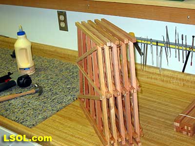
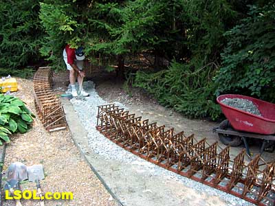
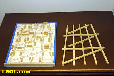
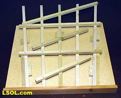
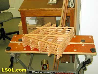
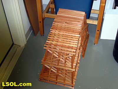
Flipping the bent over, I attached the opposite beam in the same fashion. I spent a couple of evenings and made the 50 bents. Here are the first 25.
Wood Preservative After I completed the assembly of the bents, I wanted to ensure they would last as long as possible out of doors. While cedar has natural anti-decay qualities, even 6 x 6 inch fence posts rot out over time. I found a copper based wood preservative at Lowe’s (Jasco Copper Brown Wood Preservative)
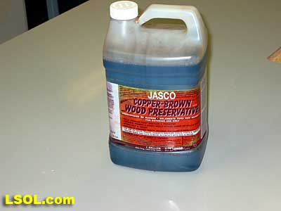
This is used optimally by soaking the bents for three minutes. Three minutes times 50 bents is 2 1/2 hours, had I done them individually! So I used a plastic storage bin that could accommodate 2 bents. It took 3 gallons of the preservative to fill the tray to a depth sufficient to fully immerse 2 bents!
The advantage to using a storage bin was that you could put a lid on it. This stuff not only looked toxic it smelled toxic too. I put 3-mil plastic sheeting down on my driveway (I did this outside, you should too) and did the soaking in the tray on top of the plastic. I wore gloves while preserving the bents.
I agitated the bents for 1 1/2 – 2 minutes then turned them over and repeated the process. I set them on the plastic to dry. After completing this step, I used a large funnel with a filter to replace the preservative in the original containers. It would be used again later in this project. It took several days before I could handle the bents without picking up the preservative smell on my hands. The upside to this process was that the bents had a nice brown-creosoted look. 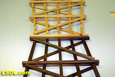
As we let the bents dry check out Part II Modular Trestle Design and Construction next week.
Top of Page