Track & Bridges
Making Turnouts For The First Time
Sep 21, 2011


By Gerald (Jerry) Madsen |
Author
Bio
I have never made a turnout for a model railway in any scale. I haven't hand laid any track other than sectional track, Flex-track, and prefab turnouts. That being said, I have come to make my very first large scale #6 turnouts.
|
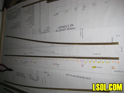
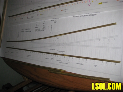
OK, I have never made a turnout for a model railway in any scale. I haven't hand laid any track other than sectional track, Flex-track, and prefab turnouts. But after downloading the PDF from LSOL.com of the #6 Turnout that was so graciously put together by Ron Hill and printing it up full size along with a reverse image for the left hand switch it really looked like a project I could do. (Link to PDF).
Then came the article in Garden Railways by Steve Monson about turnout making and it became something I just had to do. Well I liked the accuracy of Ron's drawing and the sturdiness of the bracing Steve used under the ties so after much plagiarizing of both their works I have come to make my very first large scale #6 turnouts.
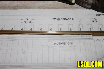
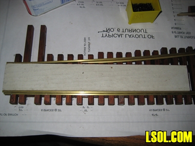
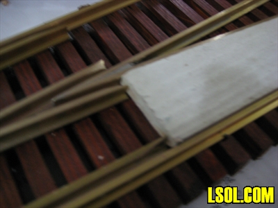
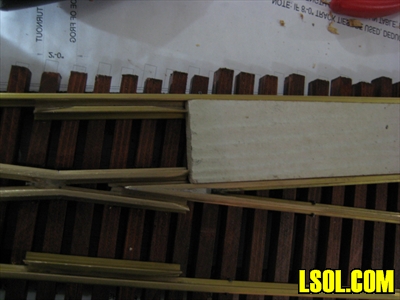
I bought a rough-cut cedar fence board and ripped the bottom supports to 7/16 inch x 7/16 inch. For the length of the bottom supports I laid them out on the LSOL PDF where the rails should be and cut them a little longer than needed knowing I could trim them in the disc sander later. The Ties I ripped to 5/16 inch wide X 7/16 inch tall. I liked the idea of extra height to make nailing to the bottom supports stronger and laying deeper in the ballast when all is done. For the length of the Ties I used the conversion chart from the LSOL PDF. When I laid out the ties and their supports I realized I needed to make some changes. First I had to separate the head ties enough to fit a large-scale ground throw. So I subtracted one of the adjacent shorter ties and separated the head ties by about 1 inch from center to center. Then I adjusted the spacing on the next 5 ties to even the gaps.
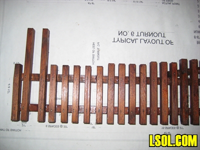
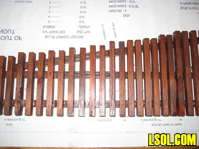
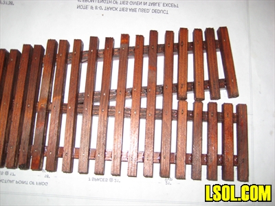
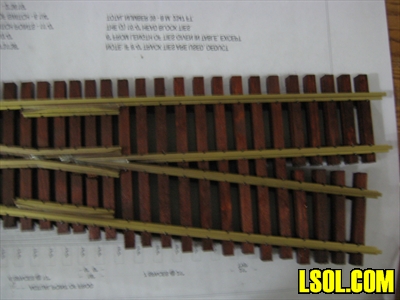
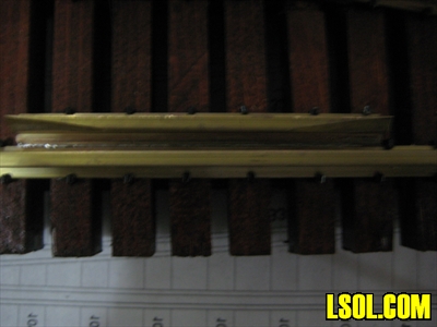
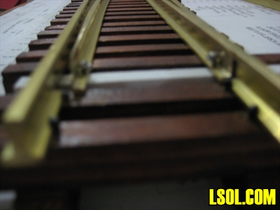
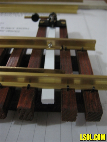
The above pics show the completed tie assembly. I did not use a jig for assembly. I just laid down the bottom supports over the rail positions on the drawing, with Titebond 3 glue and 18 gauge galvanized 3/4 inch brad nails for my Porter Cable brad nailer, nailed one tie on each end first. I used a 4-foot level as a straight edge up against those two ties I had glued and nailed the rest of the main ties first then added the divergent route ties. After a couple of days curing I sanded the tops of the ties with a sanding block and 100-grit sandpaper to ensure they were all flat and smooth. I stained the ties with Cabot Jarrah Brown oil based stain. Since this stain is oil based I made sure there was plenty of ventilation and I used disposable brushes to make cleanup easier. Unfortunately it did not turn out as brown as I thought it would, so now I have Rosewood looking ties. I used the Cabot products on my deck and trellis and really liked them but I have not found the right color for ties with it.
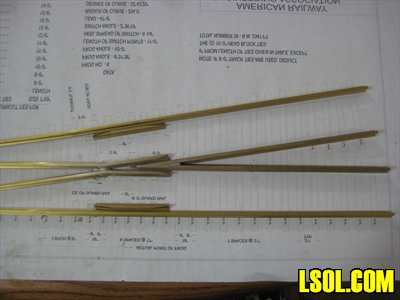
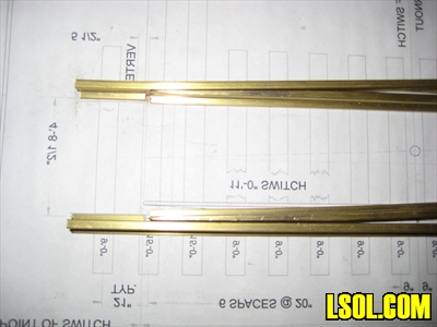
Now it's time to bend and grind some rail. I used some Brass code 332 rail that I took from some of my AML 6 foot Flex track by sliding off the plastic ties. I did not use the cut list from the PDF instead I laid out the rail on the drawing and rough cut them longer than they needed to be. This gave me a margin for error since I have never done this before and most rails could be trimmed once the critical angles and curves were established. First I cut the two long stock rails and rough bent the divergent stock rail with a rail bender. I laid them out on the drawing to see how close they were and finished bending them by hand. That is where the LSOL PDF came in handy.
Then I ground out the inside foot of both stock rails to accommodate the points. These notches should start out over the center of the first head tie. This will ensure the points have an adequate support at their ends.
I cut the guardrails to length and ground a 3/4 inch long bevel on the inside of the ends.
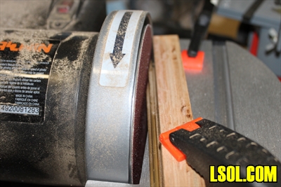
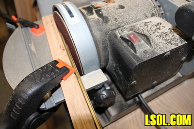
Next I cut and ground the frog through rails. I cut these extra long until I got the set up on my disc sander just right. I used a 5 inch Micro-Mark disc sander with an aluminum channel clamped to the table to sand the angles. Some trial and error later I came up with a 6-degree angle on each through rail, which got me close enough to a match on the drawing. Far be it for me to use Geometry. After further research, I learned the angle of a #6 frog is 9 degrees 30 minutes. So I divided that in half and the two frog through rail angles are 4 degrees 15 minutes. So 4 to 4.5 degrees is close enough for me.
The point to frog rails I wanted to keep in one piece for ease of manufacturing. I am running battery-powered engines so a solid metal frog won't be a problem for me. I figured at this point if I need to electrically insulate the frog I can cut gaps later and glue in some plastic fillers and then add jumper wires and a micro switch to the ground throw. I started by shaping the wing rails for the frog end. This part took me a couple of tries as I bent and rebent too many times and cracked a couple of rails until I learned patience. I tried to grind the inner edge of the wing rails bottom foot to close the gap at the frog point but that turned out to be too narrow so I settled with the bottom of the rail foot soldered edge to edge which seems to work just fine.
My test truck is exactly in gauge but has oversized flanges and worked fine. I believe the bigger gap will achieve a more reliable turnout especially if wheel sets are a little out of gauge. Once I got the length and angle of the wing rail, I ground down a bevel on the inside end about 3/4 inch. I spent the most time on the points as I gradually ground, filed, and shaped them to a rough idea of what they needed to be. I intended on finishing the profile of the points after the frog was soldered so I would have a better understanding of what to do.
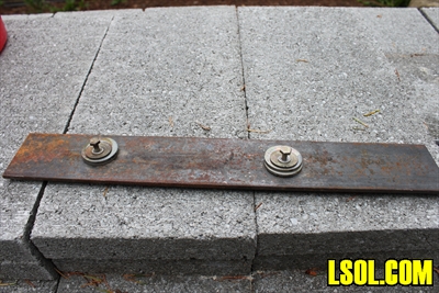
I built a jig similar to Steve Monson of Garden Railways only mine is steel because I did not have a big hunk of aluminum laying around.
Using the jig to clamp the frog through rails I soldered them first.
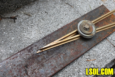
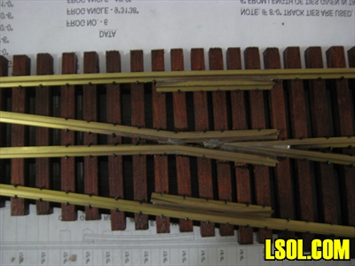
Then I clamped up the point to frog rails and soldered them to the frog through rails.
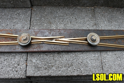
Using the LSOL PDF as a guide I marked the locations of the guardrails and soldered them to the stock rails so they were flush with the wings of the point to frog rails.
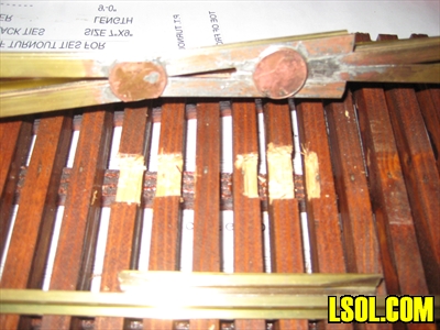
I should note at this time I would prefer a jig that holds everything at the correct angle because I had some difficulty getting all four rails soldered at the correct angle and flat at the same time. Also my steel jig soaked up a lot of the heat from the torch and made it difficult to get the rails hot enough to accept solder. In the future I might have to design a better jig to suite my style of assembly. When I got the frogs soldered to acceptable angles I soldered a couple of pennies to the bottom for strength like Steve suggested.

Using my Dremel tool I carved out the ties to allow room for the pennies to sit below the rails and then trimmed the pennies and dressed up the solder joints with a little sand paper.
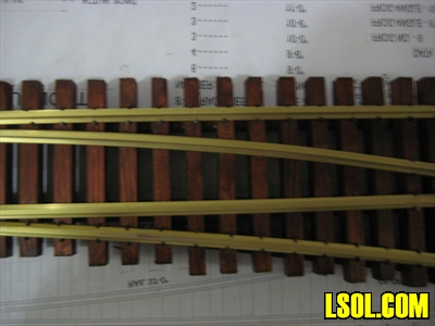
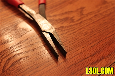
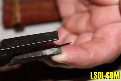
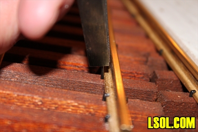
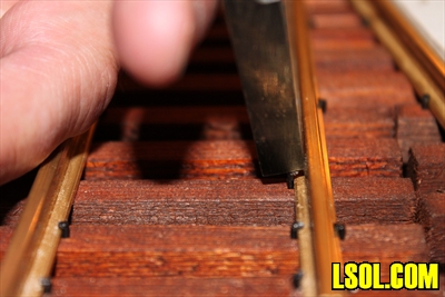
At this point I was ready to start nailing down the rails starting with the stock straight rail, which I tacked down with about 6 spikes. I use the half-inch stainless steel black-coated spikes. I insert the spikes with a pair of duck billed pliers. I like the duck billed pliers because the jaws are flat and knurled on the inside face's which is perfect for holding a spike without modifying an old pair of pliers. I should note that a pair of needle nose pliers is also used for the really tight spots around the frog. Here are a few pictures of how I spike rail.
I made a rail gage with a scrap of Hardi-Plank cement siding cut at 45mm wide and about 6 inches long. I placed the gage next to the stock rail, added the stock divergent rail, and tacked it in place at the turnout entrance end.
Next I located the frog assembly with the gage set between the stock straight rail and frog straight rail at the exit end and pinned the frog with a couple spikes.
Then I moved the gage to the divergent route and pinned those rails at the exit end of the stock divergent rail.
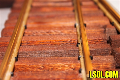
Using the gages I added more spikes to most rails keeping everything straight and in gauge. Now the points got a final filing and tuning so they seated just right. Then I finished spiking the rest of the rails to every tie.
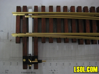
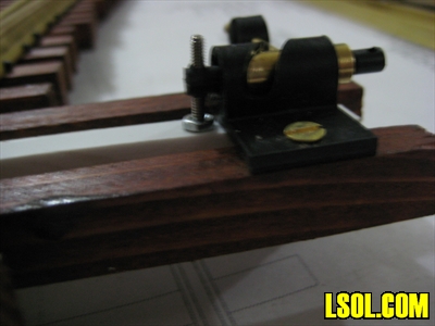
When I was happy with the gage and the way my test truck ran though the turnout I added the Tenmile switch stand. I used a 3/16 inch thick piece of styrene for the throw rod attached with some 2-56 screws. I set, drilled, and tapped the through route point first. Then I set the ground throw for the divergent route, backed the ground throw up slightly, then drilled and tapped the divergent route point. It is important to set the points on the throw rod so that the points contact the stock rails just before they are fully thrown so they have enough pressure holding them against the rails. This will prevent any flanges from "picking the points."
Since starting on this article I have obtained a certificate in Project Management so I have to leave off with a "Lessons Learned" section. It is always helpful to look back on a project and document what worked and what didn't so you and others don't make the same mistakes over.
Lessons Learned
-
I would like to add an extra tie at the entrance of the turnout for addend strength.
-
Choose a fence board with little or no knots to prevent wasted wood. You cannot push a spike through the extra hard wood around a knot without pre-drilling and that would really slow you down.
-
Finish filing the points before assembly or the filing will take many more hours and the points get very sharp so it is easy for fingers to get cut if you slip.
-
A steel jig soaks up a lot of heat so it takes longer to heat up the brass when clamped up.
-
I use Split-Jaw clamps on my rail and barely had enough rail protruding past the ties to accommodate the clamps. On my next turnouts I will make sure I have at least 1/2 inch of rail protruding past the last ties to allow ample room for the clamps.
-
Since I have a dozen or more turnouts to make I would like to make a jig for building the tie assemblies to make consistent and repeatable assemblies in a short amount of time.
-
Since I started on this article the place I bought the Tenmile ground throws has gone out of business so I have turned to the brass throws offered by Sunset Valley for my future turnouts.
Now this may not be the best or the easiest way to make turnouts. It is just a documentary on how I managed to do it with the tools, and experience, that I had at the time. I think they turned out pretty good for a first timer and I look forward to improving my assembly jig and techniques for my next set of turnouts.
| Turnouts |
| Thanks for the article. I enjoyed reading it very much. It is very well written and illustrated. Your turnouts look really nice, and will surely give years of good service. |
| Bill Ness - 09/22/2011 - 15:42 |
| Scratch Building |
| Making a turnout can be a turning point in your G-experience. Once you know how, you no longer need to be restricted pre-made frog numbers. |
| Rick Henderson - 09/22/2011 - 16:57 |
| Switch Building |
| Gerald, the switch turned out really good. Way to go! |
| Ron Hill - 09/22/2011 - 19:48 |
| Switches |
| Thanks for the kind words guys. I had a lot of fun making them. I have made a total of 13 now for the first phase of my railroad. I was glad to get the oppourtunity to share what I learned. |
| Jerry Madsen - 09/22/2011 - 20:58 |
| Switches |
| Maybe I need to go up to Jerry's house for a class on making frogs! |
| Ron Hill - 09/23/2011 - 13:52 |
| Turnouts |
| Jerry...what a great first effort. My friend was asking me about making turnouts and a few problems he had. After reading your article and step by step instructions, I can see that it answered all of those problems. Thanks for a great tutorial. Dave |
| Dave Clarke - 09/23/2011 - 17:34 |
| Turnouts |
| Jerry - great job! The turnout looks great, and the way you presented the process in your article with detailed pix is as good as it gets. Thanks. Back in the day, when I was doing model railroading on "0" gauge with my grandfather, we built all our turnouts from scratch. One of our greatest accomplishments was to build turnouts on a curve, meaning that the through rails, as well as the diverting rails, were all curved. This allows placement of turnouts in strategic places where you might need them, but don't have a long enough straight section of main line to put one in. Since these are not available from manufacturers, your article has given me a good guide to make my own. I would love to know how to wire it, since I run electrified rails. Thanks for your article. Bob |
| Bob Freeman - 09/26/2011 - 07:10 |
| Turnouts |
| Very nicely done. |
| Brent - 10/05/2011 - 09:28 |
| turnouts |
| Thanks Jerry I've almost completed four trunouts from GR plans but a couple of hints that you have given will make the next half dozen much easier. John KC |
| john k coughlan - 10/21/2011 - 23:18 |
Top of Page
|


