Track & Bridges
Improving Aristo Craft Wide Radius Turnouts
Aug 29, 2007


By Ralph Walker |
Author
Bio
Out of the box my Aristo Craft Wide Radius stainless steel turnouts were troublesome, so I developed some low-tech fixes.
|
Out of the box my Aristo Craft Wide Radius stainless steel turnouts were troublesome, so I developed some low-tech fixes. I also chose to use LGB electric switch motors and made a record of my findings during the process. Hopefully these notes will be of use when you are installing these or similar products. My outdoor layout incorporates Aristo Craft (AC) SS track and a dozen AC SS Wide Radius (10 foot diameter) Turnouts (products ART20370 Right and ART20380 Left). The turnouts are recent (2005) production, but exhibit problems which I would have thought had been cured years ago. 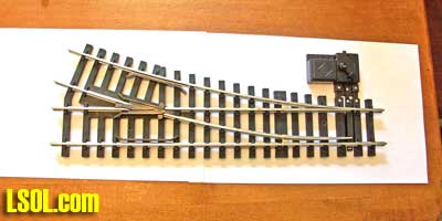 A search of the WWW and forums told me that there is no up-to-date information on modifications to these turnouts, so I will tell you my approach to beating them into submission. I have no experience with the Brass USA-style versions of these turnouts (ART30370 Right and ART30380 Left) but it is possible these notes are applicable to them. While I was doing the mods I decided to replace the manual switch machines with LGB 12010 electric switch machines, AKA "EPL Switch Drive". It seems that development of the AC 11298 'Waterproof Switch Machine' was halted. The LGB machine is NOT entirely compatible with the large radius turnouts, but it can be made to work. Again, no up-to-date information on this subject is available on the WWW, so I will explain what I know.
THE PROBLEM: The frog in the turnouts sticks up above the rails. It has to be milled to be even with them. When this is done the grooves are too shallow, letting the flanges rest on the bottom of the grooves, obviating the milling of the frog. When I ran the first trains on the layout, NOTHING went through any of the turnouts well, and I hadn't even tried switching them from the main lines. I had derailments and damage on an LGB Mikado, an AC Streamliner and an Eggliner. Some equipment stalled on the turnouts at low speed since wheels were being raised above the rails. Even the forgiving trains made a racket when traversing the turnouts, and wobbled side-to-side. I located a paper on similar problems with small-radius AC turnouts of 1999 vintage, and this was useful background information. It included some notes on the wide-radius turnouts which were new then, and their teething problems. No mention was made of the badly-formed frog, in relation to the wide-radius turnouts, though. On the smaller turnouts that author milled the tops of the frogs, in place, with an end mill. I don't even know anyone who knows anyone who has an end mill, so I needed a low tech solution. I also developed a technique for milling the bottom of the grooves which is similarly low-tech. Both processes require some elbow grease and the construction of simple jigs, but they work, and are safe and neat. After you have done one, count on 50-70 minutes to repair the frog and install an LGB switch motor, depending on whether everything goes well (that is, whether you lose any parts in the carpet).
Disassemble the turnout: You must remove the frogs to work on them. Follow these photos to disassemble the parts of the turnouts necessary to remove the frogs. You will need a #0 Phillips screwdriver, a dish for parts and a dining table. You will remove 4 kinds of screws. I will tell you which ones go where so you don't have to pay much attention to this. Turn the turnout upside down. See the photo below. 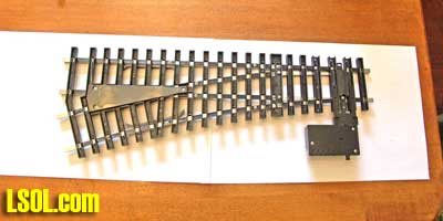 Remove the triangular cover. It is secured with 3 MEDIUM-length screws. See the photo below. 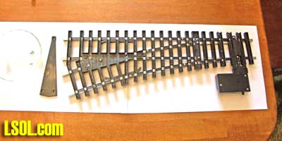
Remove two short fixed rails. These are secured with 1 each MEDIUM screws which go through wires. Note that these screws came from plain holes and not the nearby post-type holes used by the cover. See the photo below. 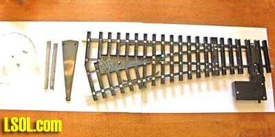 In order to remove the frog you will have to push aside one of the two rails that are tight against it. But in order to remove this rail you will first have to loosen one of the moveable points, and slide the fixed rail away from the frog. The moveable points are secured by the only LONG screw in this process. There is a microscopic spring around this screw, and a hollow brass post through which the screw runs. This post may or may not come loose during this operation. In the photo below I am loosening the screw which secures the moveable point closest to the switch motor. 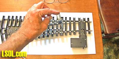
The fixed rail is secured by the only SHORT screw removed during this process. See the photo below. 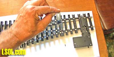 Remove the 3 SELF-TAPPING screws (photo below) that secure the frog (this was the fourth type of screw you encountered). 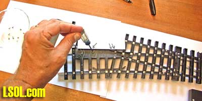
In the photo below, the fixed rail is loosened, screws are removed from the frog and the frog is ready to be slipped out. Now wiggle the frog loose. You will note that it is symmetrical and thus fits both left- and right-hand turnouts. More important to us, frogs from both types of turnouts will fit on the jig you are going to make right now. 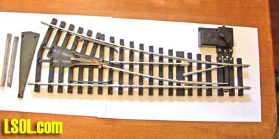 Note that the frog has 3 posts underneath. You are going to precisely drill three 11/64" holes into a piece of flat wood, snap the frog into the wood and attach two pieces of rail of the same type you are using (brass or SS) alongside the frog. To mark the positions for the 3 holes I suggest inking the frog's posts with marking pen and then quickly pressing it against the wood. Alternatively you can xerox the frog (see photo below) and lay the copy on the wood to locate the holes. These holes must be precise so if you mess up the drilling, just move to another position on the board and try again. 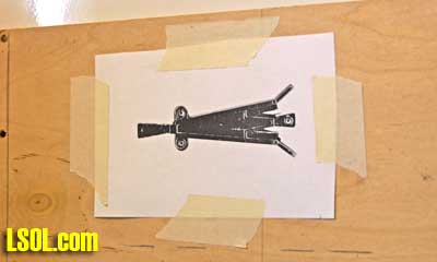
Next install the 2 rails onto the jig. If you happen to have scraps of rail with 2 holes in the bottom, use these. Or if you have the means to tap 2 holes, do that. However, a single screw is adequate to secure the rails to the wood base. Of course the wood needs to be pretty thin to utilize the original Aristo Craft screws. You must countersink these holes to avoid scarring your dining table. While drilling the countersink holes consider inserting little washers to allow for better grip. The photo below shows a frog installed on the completed jig, waiting to be milled. The reason the rails are placed as they are will be clear after the description of the process for milling the grooves, below. 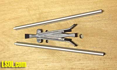 You will then put fine sandpaper on your fine dining room table and, turning this jig upside down, mill off the excess plastic by sanding it until the rails contact the sandpaper. The piece of wood must be at least 15" and should be wide enough to carry the frog and rails, but not so wide that you can't comfortably grip it during the hundreds of strokes you must make against the sandpaper. You will be making a second contraption for milling the grooves, while still holding the frog in the jig, and this is the reason the wood must be long. I suggest 20". In the photo below I have sanded the top of the frog on the wetted sandpaper and am checking my progress with a straightedge. 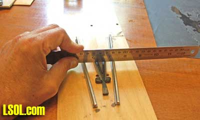
To mill the tops of the frogs I chose to start with 220 grit wet-and-dry aluminum oxide paper, which I wet. I found that good quality paper can do two frogs, provided you use one half of the paper per frog. Cheap import sandpaper could handle only one frog and I had to watch that the frog did not go through the paper as the paper deteriorated. I finished with 320 grit, leaving the tops of the frogs smooth but dull. I like the appearance. A single sheet of 320 grit will handle plenty of frogs. I could have polished them with much finer sandpaper and/or plastic polish (or Glass Wax). Simichrome would probably be a good bet also. The photo below shows the frog with the top milled to match the rails. 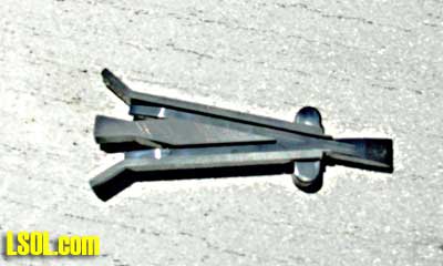 It's time to make the 2nd jig. To deepen the two grooves for the flanges I built a 'file' using four identical bimetal, 32 tpi hacksaw blades. I bought a set of 10 on ebay for $8 including shipping. You can get 3 of the identical products from your local home center for the same price (they don't have the buying power of some guy in a garage in Atlanta). This is also the correct blade for sawing rails, and you will hardly wear them out on plastic. 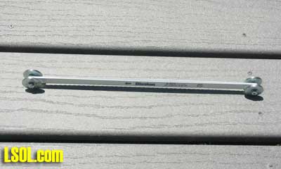
There are two holes in a hacksaw blade. I bolted my four blades together using 4mm screws, nuts, little washers and large washers. The large washers were placed outboard like wheels, though they are fixed in place. The large washers were chosen to limit the downward travel of the 'file' within the groove. In practice you just ride the file back and forth until the washers bottom out on the jig. See the photo below. 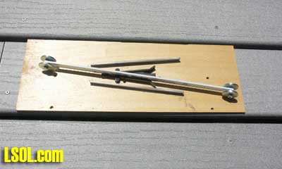 (It should now be clear why I positioned the rails in the 'V' pattern. I wanted them to be close to the frog but out of the way of the file.) I won't tell you what size large washer to use because there are variables that I don't want to be responsible for. Your frogs may have come from a different mold. Some of your train wheels may require a deeper groove (I understand the standard flange depth is .125"). Your hacksaw blades may have the holes higher or lower than mine. And the rails themselves vary a little in height. Anyway, you can see that my jig was constructed using nuts and small washers to space the large washers about 1/4" from the file, assuring that it remains upright. I was a bit disappointed that the finished bottoms were not absolutely flat but had little grooves, even though the hacksaw blads have a wavy profile. If you care about this you can dress the bottom of the grooves with a round or flat little file, or fold a coarse, stiff sheet of sandpaper in half and use it like a file. There is not much material to work with in the frog so don't go crazy deepening the grooves. I periodically tested the depth by placing the frog back in the turnout and running a wheelset over it. The finished frog was still very strong when I took out only enough material to achieve reliable and fairly quiet operation. The photo below shows the frog with the top and grooves milled. 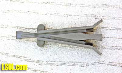 Reinstall the frog in the turnout. You have finished this modification.
INSTALLING LGB SWITCH MACHINES (time 8 minutes) As I said, no up-to-date info on this process could be found so I was flying blind. Below is a photo of the original manual AC switch machine. 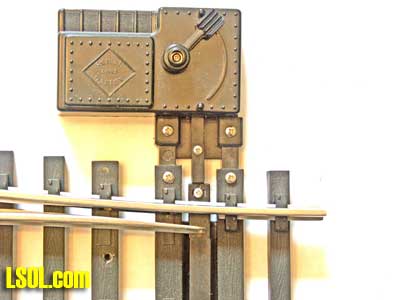 Remove the three screws securing the manual machine. Reinstall them in the manual machine for safekeeping. You will not reuse these. 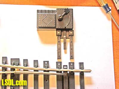 Choose the side to install the LGB machine. If you can install it on the straight side, as I did, you will not have to cut any ties, but installation on the curved side, like the original, requires the trimming of the 5th tie. I have no experience installing the machine on the curved side, so the adjustment process will be different from that described. Remove the cover of the LGB machine and lift out the actuator. Push the two mounting legs into the two appropriate ties. Do not turn the machine upside down with the cover removed or the motor and 2 bits of plastic will drop out. But if you do so you can easily figure out how they go back.
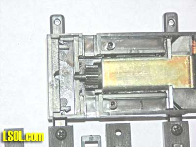 Now you will install the two self-tapping screws that came with the LGB machine through the ties and into the mounting legs. However the legs must be held tight against the ties while the screws are inserted. Because the original holes are small, and you don't want to enlarge them, the screws will tend to force the mounting legs away rather than drawing them home. Just mash the legs tight against the inside tops of the ties while installing the screws. 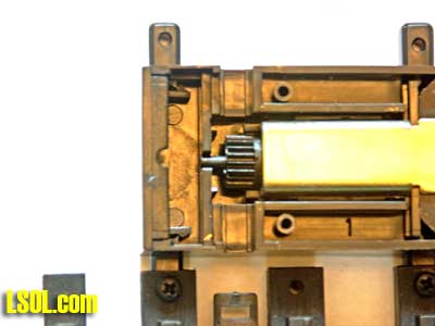 You must now install the actuator precisely. The rack gear on its underside must contact the correct tooth on the motor or the machine will not hold the points snugly closed in one of the two positions. See the photo below. There is an incompatibility between the LGB machine and the AC turnout. The travel required to throw the turnout is smaller than the machine's designed travel. Since the greatest force for holding the turnout in one position or the other is exerted at the end of the machine's travel, the turnout can never be held strongly. The only way this machine can even work adequately in both positions is if you adjust it to exert exactly the same pressure both ways. With care in adjustment they can exert just enough force to adequately hold the position of the turnout when subjected to vibration. (At this point I'd like to say that a clever person could devise an alternate mounting scheme to allow the full travel of the LGB machine. In fact I have one in mind, but it would require modification (mutilation) of both of these devices, and your widow could never sell them on ebay. . . .)
Here is my technique for equalizing the machine's actuating arm force. Move the gear to its center position, indicated by the little stop in the upright position. It will stay in place. Move the points so that the space between the straight rail and the adjacent movable point is half that of the space between the curved rail and its adjacent movable point. This position was derived by trial and error. Any other position chosen at this point results in uneven pressure between the two turnout positions. But you are free to try to improve on my results. Drop the actuator in place. It will look like this: 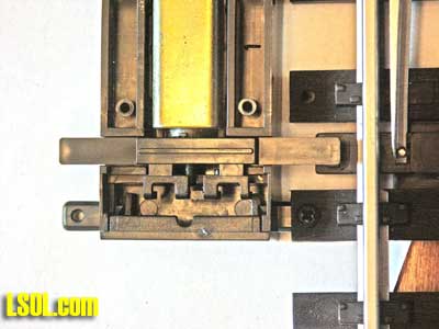 Press the cover in place on the machine (but don't reinstall the screws) and try moving the points. (LGB machines simply hold the points in whatever position they were last moved to). If the pressure is adequate in both positions you are done. Install the four screws. After the turnout is installed you may wish to apply some sealant on top of the screws that secure the wires (rubber cement, silicone, hot glue). If the switch is not behaving, repeat the process, varying the initial position of the points. The bigger the gap on the straight rail side, the weaker the points will be when switched to the main line. Actually, using my method there is a slight bias towards good performance on the main line. The photo below shows the installed machine. 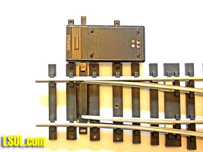 You are done. It's time to wire the machine. I don't want to get into the controversy about what type of current is required for these (half-wave AC vs DC, continuous vs momentary). That's another story. Top of Page
|


