Track & Bridges
Build a Simple Switch Indicator
Jul 9, 2008


By Kirke Fay |
Author
Bio
Our project for this "How to" article, is going to be making a target indicator, which will have two blades, mounted on a brass post, that will slip into the hole that holds the lantern provided in the Aristo manual right and left hand switches.
|
It's a fact of life: If you have track on a railroad, there is going to be a switch located somewhere. On most railroads the switches are going to have the switch throw, which will have a pivoting rod holding a set of blades that are going to be painted contrasting bright colors or have a four-lens lamp (for night time use) or both. These are used by railroad personnel to confirm the position of the switch, if it is in a "straight through" position (usually green is the indicator color) or "thrown" to lead into a secondary track or siding, of which the color would likely be red. 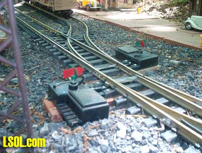 Our project for this "How to" article, is going to be making a target indicator, which will have two blades, mounted on a brass post, that will slip into the hole that holds the lantern provided in the Aristo manual right and left hand switches. Other manufacturers of switches do not have this provision. This hole or recess in the top of the switch stand has a Philips screw recessed into it, and as you will see, will not be altered. What we are going to do is make our replacement for the dummy hard to see lantern provided, out of two pieces of copper and one brass wood screw with all three pieces sweat-soldered together in one unit. Simple? You bet!
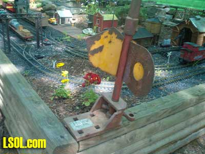 01 - This is one of many shapes of the target indicator blades. Notice that the shaft at the top is shaped in a rectangle to accommodate a lantern that would have a corresponding slot in the bottom of it. The colors on this antique could indicate its use as a derail signal not a switch.
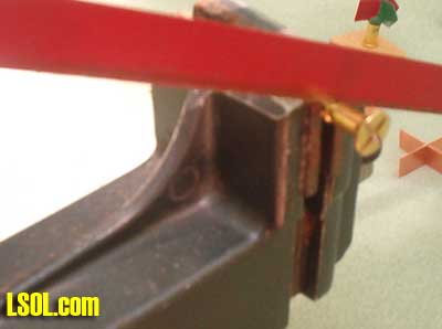
02 - Here are two of the target switch indicators that we are going to make, in use on the D.B.& H. Rwy. Notice the colors match the position of the switches.
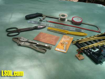 03 - A collection of the parts and tools needed, but just tin snips and a hobby saw, a ruler, and solder are the very basic tools. For your materials, sheet copper (from Michael's Craft Stores in the mid-Atlantic region) some brass woodscrews, flat-headed, # 10 size by 1 inch long. A number 8 or 12 size screw will be either too large or too small for our use.
 04 - Place your brass flat head screw in your vise, and cut through the center of the top with a hacksaw/thick-bladed hobby saw, giving you an "X" shaped notch into the screw head.
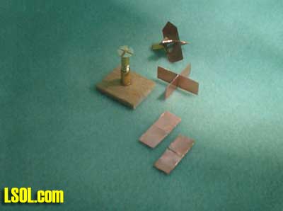 05 - A view of the completed screw after cutting. Also shown are the basic parts in the three steps.
 06 - At this point, cut off the screw threads at the end of the smooth shank.
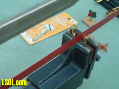
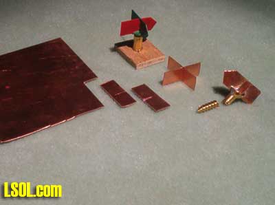 07 - Here are the materials used, and shown in each stage of construction. At the left is the copper sheet. On the sheet, mark off in pencil or scribe the dimensions of the target blades which are: 1 inch long x 3/8" wide. Mark in the middle of the 1" wide section, the center line which will be your guide to cut halfway through the two pieces. These two pieces will slide into each other, and may need a slightly wider cut than the snips or the saw has produced. With the two copper pieces notched and fitted together to form an "X", place them into the corresponding notches on top of the brass screw. The brass screw should be gripped by a metal vice or a set of vice-grip pliers at the base, and heat applied from either propane or butane torch to allow the solder to flow into the slots and also sweat the blades together where they join. After cooling, straighten as needed, and a point could be cut into two of the ends (see pictures).. A notch could be added to the opposite ends, if desired to enhance the arrow indication.
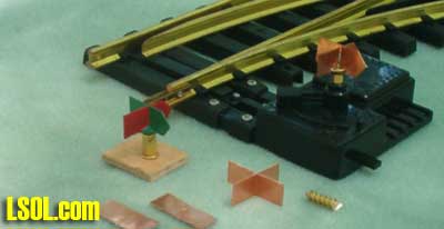 08 - The finished and unpainted targets are shown on an Aristo-Craft #11205 right hand switch. The target when completed by painting, will be fastened into the hole/receptacle with a drop of "Goop" or glue of that type, to allow the removal of the target without damage to either the switch or the target. You will find that the # 10 size is a tad loose, and as it must pivot to work, thence is the reason for the glue. Different shaped blades were used by different railroads. Round, Round-cornered, reflector lenses attached to the blades, or with a lamp on the top for night-time operations was all common. (You could notch the bottom of the Aristo-supplied lamp and fasten it to the top of the target) I spray painted the entire target a bright green enamel and then hand-painted the opposing blades bright red. My size selection is based on keeping within a large scale size, but large enough to see from a distance.
| Really like your article |
| Really like your article. Can you come up with one to fit the LGB switch machine? I know it does not have the same attachemnt for the indicator, but how about some kind of cam to move the indicator? |
| Dennis Cherry - 07/14/2008 - 07:49 |
| LGB switch stand |
| I have two LGB switches and with your propmpting, I took one apart to study the workings. I did come up with a possible answer, that would indicate the switch position. If you're interested and love to tinker, I'll make a drawing of the mechanical hookup....are you aquainted with a "Harp Throw" switchstand ?....I can make a picture of the drawing so maybe you'll be able to come up with the parts to make what you need. (this is an indicator that will swing to the right or left, and not pivot)Send me your home e-mail address and I'll send the drawing and pictures to you, along with my suggestions. No, it won't alter the LGB switch except maybe a couple small screws in the cover plate. |
| Kirke Fay - 07/14/2008 - 18:49 |
Top of Page
|


