Comparing the EBA-101 and EMP-103 Motor Controls The RCS throttle system consists of a shirt pocket size transmitter, receiver, and a control module, which controls speed, direction and accessories. The module has connections for controlling a sound system: whistle, bell, and one additional auxiliary.
The RCS system uses a memory feature to keep the engine at the selected speed and direction. You only have to transmit a signal when you want to change either one. This helps to eliminate glitching that could result if a continuous signal was needed.
We were given one of the prototype RCS 5-amp throttle units [EBA-101] to evaluate, and later we were given one of the new production 5-amp EMP-103 units that replaced the EBA-101.
What do you get?
Our sample unit included a transmitter, receiver, a power control unit, some chokes, capacitors and a power control switch unit.
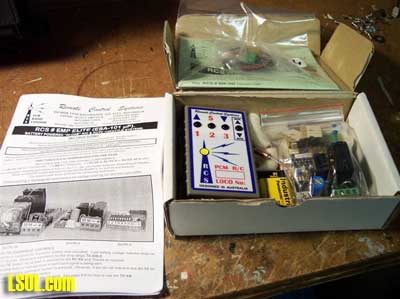
It was packed in a cardboard box and included a 12 page instruction manual.
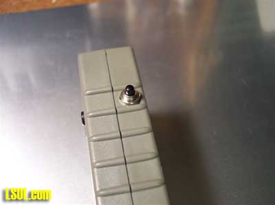
The transmitter measures 3 3/4" x 2 1/4" x 7/8" and has no external antenna. The transmitter's batteries are installed from the rear of the unit [413] a battery cover slides off to reveal where a single 9v battery is installed. 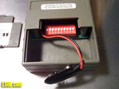
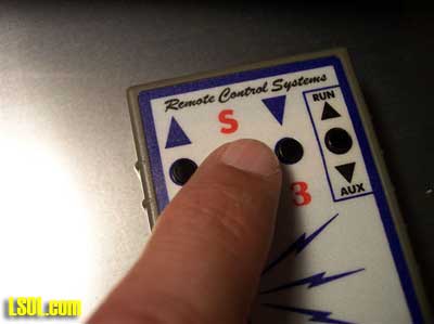
The transmitter has four [4] buttons on the front and one button on the side.
There are multiple functions associated with these buttons and their functions depend upon how you set up the programming for the unit. When in basic mode the number one button speeds up and the number 3 button slows the unit down.
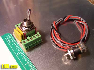
The power control switch unit measures 1" x 7/8" x 1 1/2" - to the mounting point of the toggle switch. 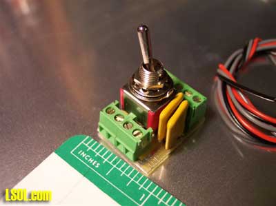
There are two groups of screw down connectors for the connections to the batteries, charging port and output to the control unit.
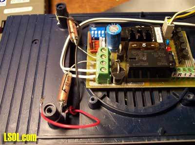
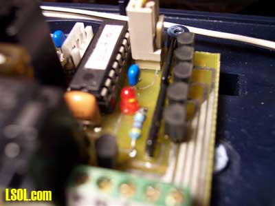
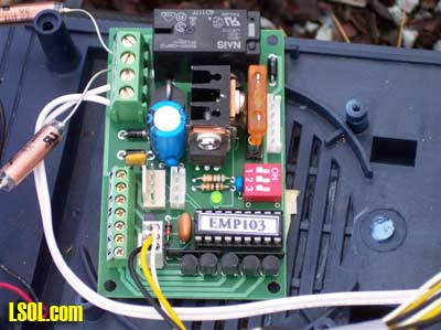
The throttle module controls the speed and direction as well as provides the auxiliary outputs for sound. The unit measures 2" x 3" x 7/8".
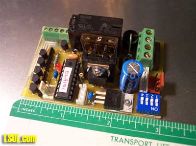
It has a number of plug ports and two screw down wire connection strips.
and has a replaceable 5-amp fuse installed on the board.
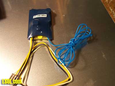
The receiver unit measures 2" x 1 3/8" and is 1/2" thick.
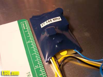
There is a plug in connector on the receiver that gets plugged into the control unit and an antenna wire that is 32" long. All the wiring connections are clearly labeled and the included wiring diagram is very easy to follow. When wiring the test bed engine I also used the U-BIK power switch and charging jack controller.
This is designed to make it easy to wire onboard batteries into your engine and the charging jack makes it easy to charge batteries while in your locomotive. It serves as an on-off switch and switches the batteries for charging from the power plug.
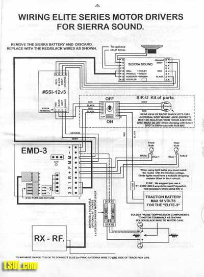
The control unit is compatible with any sound card on the market; and RCS makes an adapter board. (part# SSI-12v3)
with an opto-isolator to make it easy to connect the unit to a Sierra sound card. It also includes a power adapter, which allows the elimination of the small gel-cell battery which comes with the Sierra sound system so the sound card will run on main battery power.
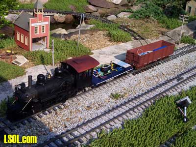
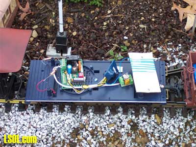
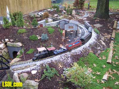
Testing the unit Like our other tests, to evaluate this unit we rigged a test bed using a Bachmann 10th anniversary 10 wheeler with a spare tender and an auxiliary battery car.
Hooking It Up
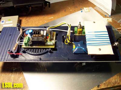
First, we connected the power leads from the battery car to the power switch with its power plug and connected the output to input on the power control unit. We then connected to output to the motor leads with one choke inline on each motor power lead.
Next the receiver was plugged into the control unit [429]. Finally we used the same piece of cardboard from our other test bed to wrap the antenna lead around [427]. I opted not to install the capacitors, as I didn't want to open up the test engine since they are usually installed right next to the motor. If I was doing a permanent install however, I would. The test unit with the engine, tender and battery car was then taken outside for some test running.
Programming This is where the RCS system really stands out from the rest of the crowd, there are 4 different throttle run modes, with options how the throttle operates in each of the modes.
BASIC CENTER OFF: In this mode the forward button will accelerate the engine forwards, the rearward button will slow the engine. If you hold the rearward button long enough the engine will stop, but it will not go into reverse until you release the button for one second.
FULL CENTER OFF: In this mode the throttle works the same as BASIC CENTER OFF with a few additional features. The "S" button will stop the engine at a fast rate. There is also a "Kadee" switching feature where the engine will stop quickly during the last 30% of stopping so that if you are pushing cars with uncoupled Kadee couplers they will not accidentally recouple when you stop.
POSI-CHANGE: In this mode the forward button accelerates and the rearward button decelerates, but you use the run/aux button to change direction. The "S" button will stop the engine in 5 seconds.
FULLY AUTOMATIC: In this mode reed switches and magnets control the locomotive. It can be set up to soft stop and soft start while maintaining the same direction, or it can be set up to soft stop, reverse and soft start in the opposite direction.
Basic Programming: There are DIP stitches in the transmitter that can be set to any desired combination to create a unique code for your transmitter.
If you have more than one transmitter you would want to use different codes in each one. To link the throttle controller and transmitter for the first time you need to set dipswitch number 9 on the transmitter to "on".
Turn on the receiver and press the "S" button on the transmitter. The light on the receiver will flash to indicate acceptance of the code, now turn dipswitch number 9 back to "off" and you are ready to go.
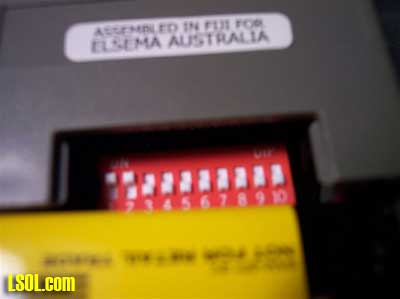
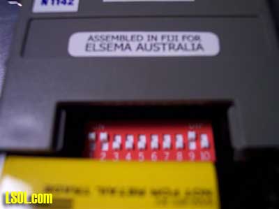
The DIP switches on the receiver can be set to program the control mode you want to use, in addition you can program the acceleration rate, and if you want the whistle, bell and auxiliary controls to be momentary or latching. In addition you can set the maximum speed to 100%, 75%, 50% or 25%, and the dwell time when the locomotive is stopped [in automatic mode only].
Evaluation of controls The basic throttle controls are using the 1st and 3rd buttons. When the buttons are depressed the transmitter emits a low frequency hum that lets you know the unit is operating. The "shift" button on the side of the transmitter makes the number 1, 2 & 3 push buttons on the front function as sound controls.
"Kadee Function" - This feature assists in the operation of Kadee couplers by making the last 30% of deceleration rapid which in turn makes the slack from run out when stopping. This is useful when using the delayed coupling feature of Kadee couplers as this helps prevent accidental recoupling. I played around with this when testing my test bed engine, as I have Kadees on my layout, and it does work!
I tried all but the automatic modes and found I personally liked the "Full Center Off" mode the best. I found the throttle to be smooth and responsive and it was easy to control the speed and direction.
Range
I found that the unit operated very reliably until I reached a distance of about 90 feet. Beyond that point the unit would operate with reduced reliability, although I could increase the range up to 105 feet by holding the transmitter higher. We did not encounter any glitching while we were running our test bed engine. The range could be further enhanced if the antenna lead is run out thru the wheels and conducted out to the track rails using a track pickup.
The instructions also recommend installing a metal rod [antenna] and wiring it to the track too. This in effect makes all the rails into a big antenna, but it should only be done if you are using battery power exclusively, I would not recommend doing this if you use both track power and battery power.
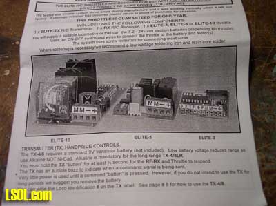
The New Elite EMP-103 Motor Controller Shortly after I had reviewed the EBA-101 and had started this article Don Sweet from RCS sent me one of his newly upgraded 5 amp motor control units [EMP-103]. I set this unit up on the same test bed and tried it out too.
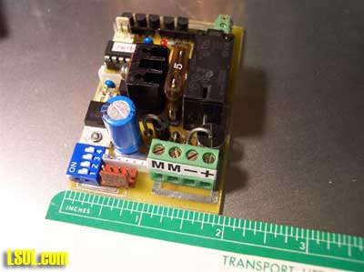
I was able to use the same transmitter, and receiver and the dimensions of the new EMP-103 board are the same as the original EBA-101. The orientations of some of the screw down connectors are different and the new board only has three DIP switched instead of the original boards four but it is otherwise identical.
When wiring the test bed engine I again used the U-BIK power switch and charging jack controller.
The new EMP-103 control unit is also compatible with any sound card on the market; and the same opto-isolator adapter board [part# SSI-12v3] can be used with Sierra sound cards.
Testing the unit Like our other tests, to evaluate this unit we rigged a test bed using a Bachmann 10th anniversary 10 wheeler with a spare tender and an auxiliary battery car.
Programming
The new EMP-103 units allows for three different throttle run modes, with options how the throttle operates in each of the modes.
BASIC CENTER OFF: In this mode the forward button will accelerate the engine forwards, the rearward button will slow the engine. If you hold the rearward button long enough the engine will stop, but it will not go into reverse until you release the button for one second. The "S" button will stop at the fast rate. The "Run/Aux" button controls if the whistle is momentary or latch on/latch off. Also the bell and auxiliary sounds can be triggered automatically by specific throttle changes.
ELITE CENTER OFF: In this mode the throttle works the same as BASIC CENTER OFF with a few additional features. The "S" button will stop the engine at a fast rate. There is also a "Kadee" switching feature where the engine will stop quickly during the last 25% of stopping so that if you are pushing cars with uncoupled Kadee couplers they will not accidentally recouple when you stop, this is activated with the "Run/Aux" button. The sound controls are operated by pressing the shift button and pressing button one for whistle, button two for bell, button 3 for auxiliary, and the "Run/Aux" button will turn the lights on and off. All the sound functions can be programmed for momentary or latch on/latch off depending on the sound system you are using.
FULLY AUTOMATIC: In this mode reed switches and magnets control the locomotive. It can be set up to soft stop and soft start while maintaining the same direction, or it can be set up to soft stop, reverse and soft start in the opposite direction.
Basic Programming: The transmitter and receiver are liked using the same method described previously for the EBA-101. You also used the DIP stitches in the receiver to set the operating mode, momentum, maximum speed and sound control options similar to the EBA-101.
Evaluation of controls
I was happy to see RCS retained the operating features of the "Full Center Off" mode of the EBA-101, as the "Elite Center Off" of the EMP-103 worked the same way. I found the new throttle to be just as smooth and responsive as the EBA-101 and it was easy to control the speed and direction.
Range
I found that the EMP-103 operated very reliably until I reached a distance of about 80 feet. Beyond that point the unit would operate with reduced reliability, although I could increase the range up to 90 feet by holding the transmitter higher. We did not encounter any glitching while we were running our test bed engine. Just like the EBA-101 the range could be further enhanced if the antenna lead is run out thru the wheels and conducted to the track rails using a track pickup.
Wiring
The modular design and accessory boards makes the RCS system a simple install for even a first timer. With screw down wire connectors the only soldering that might be necessary would be changing the wiring inside the engine.
Contact:
RCS of New England
34 Fairway Dr.
Merrimack, NH 03054
Tel: 603-424-5078
Fax: 603-424-6897
www.remotecontrolthrottles.com
Retail Prices:
Elite 3 3 amp controller, receiver and transmitter $300
Elite 5 5 amp controller, receiver and transmitter $325
Elite 10 10 amp controller, receiver and transmitter $350
TX-8-LR Extra Transmitter $110
Accessories:
U-BIK Basic Battery Install kit w/charge jack $20
BIK-U Screw terminal Battery Install Kit w/charge jack $35
BIK-UDE Same as BIK-U, 2 charge jacks for Diesel ends $40
BIK-U+VC Same as BIK-U, w/volume control $50
BIK-TC Complete Battery Install Kit for a trailer car $50
PDB Mini-Power distribution board w/Screws terminals $10
HU-WIRE Pack of Hook -up wire $10
RF-CHK Two chokes w/caps, mounted on pcb w/terminals $15
RELAY-U Lighting Relay Board w/ 15v regulator $30
SSI-12v2 Sierra Sound Interface board & battery eliminator $40
Pros:
Small Transmitter that will fit in your shirt pocket
No external antenna on transmitter
Very Good Range
Screw down connectors for wires
Great flexibility in programming and setup
Optional automatic control via magnets and reed switches
Build in LED on control board to make programming easy
Power switch module with power plug available [part #U-BIK] Simple to wire and install
Cons:
Requires Optoisolator for use with Sierra sound card [part #SSI-12V2]
One transmitter required per engine
Coming up:
We will be evaluating the onboard control system from Aristocraft and a final side-by-side comparison of all three manufacturers. Then we will show you some step-by-step installations in various engines.
Top of Page