Power, Sound, R/C
:
Remote Control
Build a Radio Control / Battery Car
Apr 27, 2005


By Llyn Rice |
Author
Bio
Although track power is still the predominant method for powering and controlling garden railway trains, battery powered radio control is gaining in popularity.
|
Although track power is still the predominant method for powering and controlling garden railway trains, battery powered radio control is gaining in popularity. One means of setting up such a system is to put the radio control receiver and batteries in a car that will trail the engine. This allows the use of large capacity batteries for longer run times between charges and a single trailing car can be used with several different locomotives. This article is for those modelers who want to give battery-powered radio control a try. Because there are all sorts of options for building a radio control / battery car, I will show you how I did mine so that you will have enough information to build yours. Rather than trying to exactly copy what I've done, consider what might work best for you and try experimenting. Because I model modern standard gauge trains in 1:29 scale, I chose to use an Aristo-Craft Evans boxcar. Before starting work, I listed the features I wanted to have in my radio control / battery car. They were: Long Run Time - I wanted long run times with up to two Aristo-Craft Dash 9 diesels and chose nickel metal hydride (NiMH) batteries because they have excellent power density. An Internet search turned up some 11,000 milliamp hour D cell batteries. Twelve cells yielded 14.4 volts, allowing a medium operating engine speed, appropriate for a small, regional railroad. For high-speed inter-modal freights or passenger trains, you might want to consider using 16 cells for 19.2 volts. Easy Access - The car had to be easy to get into to access the power switch, fuses and charging jack. I chose to mount all of the equipment to the chassis of the car and have the box simply lift off. Control More than One Locomotive - The radio control receiver had to handle the current draw of at least two Aristo-Craft Dash 9 Diesels with the possibility of adding more similar size locos later. I chose to go with the Aristo-Craft Trackside Train Engineer receiver (CRE55471) that can control up to 10 amps. The TE is widely available and competitively priced. There are other radio control systems which can handle 10 amps and any one of them could be substituted in this project.
Before installing the radio control receiver and batteries, the car had to be prepared by adding ball bearings to the trucks, stiffening the chassis and creating clearances in the box car body. I recommend that you install bearings in the trucks because a car filled with batteries can be quite heavy. The wheel axles are steel and they run in bronze bushings in the truck side frames. These friction bearings will cause drag and wear quickly. The very first thing I did was to install Aristo-Craft #29411 Ball Bearings. My car came equipped with metal wheels, but the newer Evans boxcars are being shipped with plastic wheels that should be exchanged for metal replacement wheels. To install the ball bearings I disassembled each truck. I popped all of the rotating caps off of the axels as shown here 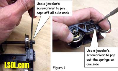 Then using a jeweler's screwdriver I took the springs out of one side of the truck. Although I took my chances, some modelers like to tie a bit of thread to each spring before removing it to keep it from flying away. Once the springs were safely out, I slid the bolster down and pulled it out of the side frame as shown here 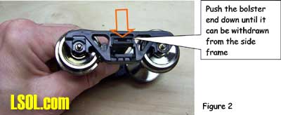
I removed the wheel sets and pressed the bronze bushings out of the side frames as shown here. 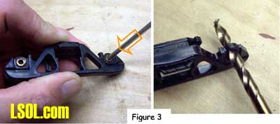 The factory apparently puts a bit of glue on the bronze bushings and I sometimes needed to grab the flanges with pliers and twist gently to first break the bond. Then, I drilled the bushing holes to fit the ball bearings. The bearings have an outside diameter of 6 millimeters. If you do not have a 6mm drill, a 15/64" diameter bit is very close. Be gentle with your drilling. I used a drill chuck from my lathe's tailstock to let me drill by hand. You should be able to press the bearings in with gentle pressure. 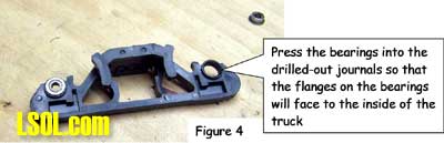 If they resist, use the drill bit to open the tight hole(s) until you achieve a good fit. The trucks were now reassembled by reversing the disassembly process. The bearings made a remarkable reduction in rolling resistance. Be careful where you put your finished car down. If the surface is not really level, your car will disappear over an edge. The next step is to modify the car's chassis. I always body mount Kadee #789 couplers on my cars and I did this with my radio control / battery car. Whether to make such a conversion is a matter of personal preference and this conversion will work just fine by keeping the factory-installed truck-mounted couplers.
The next step and the key chassis modification is to stiffen the floor. The floor platform is very limber and relies on being screwed to the box car body for stiffness. Since I plan to lift the boxcar body off frequently and did not want to remove and reinstall screws each time, I needed to find another means to stiffen the chassis. First, I removed the box car body from the chassis by removing the six screws that held it in place. Then, I measured the chassis and chose to cut a stiffener from a piece of 2 X 4 lumber. The stiffener could have been some other material such as aluminum angle irons. However, in order to avoid interfering with the radio control receiver antenna, I chose to avoid any sort of metal and used wood. 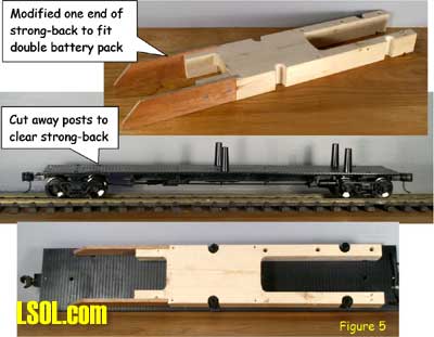 Take a look above at the stiffener, the chassis modifications to accommodate the stiffener and how they looked when mated. In order to secure the stiffener, I drilled up through the floor and secured it with screws.
To keep the screw heads from pulling up through the soft plastic floor, it is necessary to use washers or a mending plates as shown here. 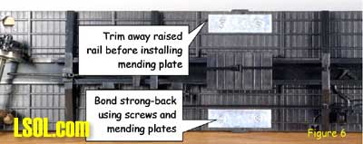 The raised under-floor ribs have to be trimmed flush with the floor before installing the mending plates. I found my mending plates in a hardware store in the same rack with angle irons. The mending plates are rectangular steel straps with countersunk holes already drilled in them and looked as if they would be a neater fit than circular washers. As it came from the factory, the boxcar body was secured to the chassis by six screws that extended up through the floor into six studs that were molded into the sides of the box. When I installed the Trackside TE receiver, it interfered with the middle studs. I cut away the studs and their supporting webs to a length of one and one quarter inches as shown here. 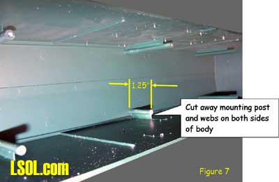 Finally, the Evans car was ready to begin installing the electronics. This consisted of mounting the receiver, adding input and output wiring, preparing the battery packs and installing the antenna.
I chose the Aristo-Craft trackside TE over their on-board TE receiver (CRE55490) because the trackside TE can handle 10 amps and the on-board TE only about 2 amps. Only the trackside TE receiver would meet my power requirements. In order to get the Trackside TE receiver to fit in the available space, I removed the circuit card assembly from the case. There were four screws in the bottom of the case. I removed them and separated the upper and lower pieces of the case and removed the circuit card. I mounted the circuit card on top of the stiffener by using four screws. Because the bottom of the circuit card was not completely flat, I used four plastic spacers I found in the local hardware store to raise the circuit card a bit. 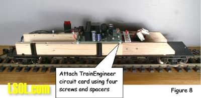 In order to wire the battery pack to the TE receiver, I used a Double-Pole / Double-Throw (DPDT) switch to hook up the batteries so that they could be connected either to the battery charging jack or to the TE receiver as shown here. 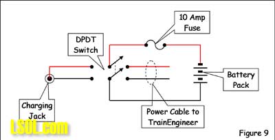 Flipping the switch to the charging jack position turns the TE receiver off. Please note that the positive battery terminal must connect to the red input wire on the TE receiver. Reversing the wires will prevent it from functioning.
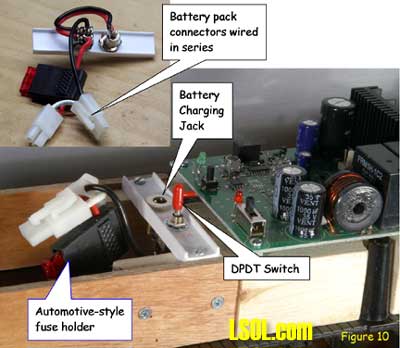 Look at the picture above to see the power feed hardware I used. I mounted the charging jack and switch on a piece of 5/8" plastic I beam. I could have used any DPDT switch; but it had to be rated for at least 10 amps. The charging jack was a Type M, panel-mount, coaxial unit (Part number 274-1563) from RadioShack. I also found an automotive type fuse holder at RadioShack. I used toy car battery connectors from Digi-Key to connect my battery packs. They consisted of a molded plastic plug (WM2308-ND) and receptacle (WM2309-ND) into which I inserted metal sockets (WM2311-ND) and pins (WM2310-ND). They are compatible with the plugs on the RadioShack racing car batteries if you choose to use them instead of the ones I used. For my project, I divided the battery cells into two packs that I wired in series. That is why the picture shows two plugs wired in series. Some modelers have challenged me for putting a fuse in the battery circuit because the Train Engineer has a built-in fuse. I once shorted out a battery wire that glowed red hot and almost burned down a prized model. Since then, I've always added a fuse as close to the batteries as I can get it. There were several choices for battery type, size and capacity. I chose to use Nickel Metal Hydride (NiMH) batteries because they are a well-established technology and have a very high power density for their size and weight. By searching the Internet, I found some Powerex 11,000 milliamp-hour D cells and bought twelve to yield 14.4 volts.
I bought mine from ZBattery.com, 1826 Hilltop Road, Saint Joseph, MI 49085 which is one of several sources. If you enter "D Cell NiMH 11000 Powerex" into Google, it will lead you to several vendors to choose among. The largest battery holders I could find held four cells each. So, in order to divide up the twelve cells, I put one holder at one end of the car. I bonded the other two holders together with glue, wired them in parallel and put them at the other end of the car. 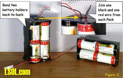 This set of batteries stores a lot of power. At a flower show, I used this radio control / battery car to power an Aristo-Craft Dash 9 and five cars for 4.5 hours and the batteries still weren't run down. The antenna that comes with the Train Engineer is a 37 inch long piece of flexible wire. In order for it to provide the best possible reception, it needed to be mounted as high in the radio control / battery car as possible. The antenna works best if it is kept straight, kept separated from heavy metal parts and, if it must be coiled, the wire must not cross over itself. Battery cars are never long enough to leave the antenna straight, so you must compromise. Some modelers who use hopper cars or gondolas glue or tape the wire around the perimeter of the car near the top. Others cut a piece of cardboard nearly as wide and long as the car and wrap the wire around that with the turns widely spaced. I decided that, because I wanted to be able to lift the box car body off easily and still have the antenna high in the car, I would use 12-gauge solid copper wire stripped from a length of household wiring cable. I cut it 36 inches long and put a push-spade connector at one end.
I then made up four support posts of 5/8" plastic I beam, formed the wire and mounted it as shown in Figure 12. I left a one-inch piece of antenna wire on the Train Engineer circuit board and installed a connector to mate with the push-spade on the antenna as shown in this inset view. 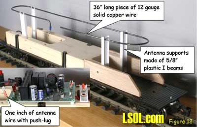 This has been very successful. I have very good control out to 50 feet and it works out to beyond 80 feet if I hold the transmitter above my head. Finally, I needed to connect my radio control / battery car to my locomotive. If you have an Aristo-Craft locomotive with a battery connector on it, you may want to consider buying an Aristo-Craft MU Cable (part number 29607). If you cut the connector from one end and solder on wire extensions, you can use this to connect to the plug on the locomotive.
I decided to design and make my own cable connections, because I liked the appearance better. Also if your locomotive is an older Aristo-Craft product that does not have a battery plug or it came from a different manufacturer, you should consider using the same connections I made for my car. 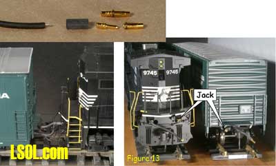 I searched the Internet and found some MP Jet 2.5mm connectors which radio control airplane modelers use to hook up electric motors. (You can find these connectors at www.azarr.com or www.hobby-lobby.com). I then chose some test probe wire (RadioShack part number 278-564) which had a thick insulation and wire with numerous, small strands producing a supple, tough cable. I installed the connecting wiring so that there was one wire with a plug and one fixed jack on both the radio control / battery car and the locomotive as shown above. This arrangement ensures that the wires can be connected only one way and that the locomotive will always move forward when the right direction button on the Train Engineer transmitter is pushed. I put a wire and jack on both ends of the locomotive so that it could run with either end forward.
You need to make the wires long enough that they don't pull tight or tug while going around curves to avoid fatigue failures to the wire. I initially made the locomotive wire a bit short and supported the radio control / battery car jack by the wire just behind it as shown here. 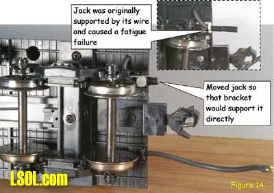 This shorter wire led to a fatigue failure just behind the jack. To solve this problem, I made the locomotive wire longer and relocated the jack so that the bracket supports it directly. One feature I like about this wiring design is that the wire on the locomotive, when not in use, can be arranged to look like a stored MU cable as shown here 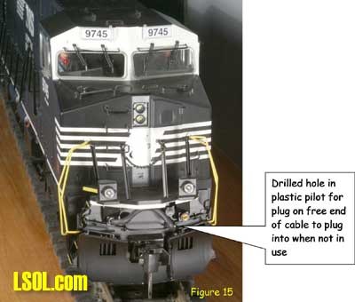 CAUTION: I drilled a hole in the locomotive's plastic pilot into which to insert the plug at the free end of the cable when not in use. If you put the plug into the electrical jack, it will short circuit the system.
At this point it was time to put it all together and check it out. So, I set the DPDT switch to the "Charge" position so that the Train Engineer receiver would initially be off and hooked up the batteries. 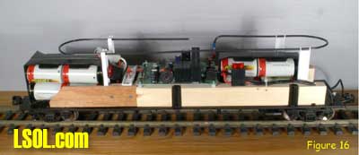 Take a look at how my radio control / battery car looked with the batteries in place. I found that the batteries can jiggle out of their holders, so I wrapped some tape around the holders to keep the batteries in. To check out the system, I connected the radio control / battery car to my locomotive. I moved the slide switch on the Train Engineer receiver to the "On" position. You can set the pulse width power / linear power selector switch for whichever type of output you prefer for your locomotive. I chose pulse width power. Because the switches are not labeled on the printed circuit card, I needed to look at the markings on the Train Engineer receiver case to determine which direction each switch should be thrown. I turned the DPDT switch to the "Run" position and programmed the Train Engineer receiver in accordance with the Aristo-Craft manual. My locomotive now ran under control from my radio control / battery car. I wanted my locomotive to move forward when I pushed the right direction button on the transmitter and it did just that. Had it run backwards, I would have interchanged the wires to the receiver output terminals.
Based on my experience, so far, a fully charged set of batteries should allow you to run one large engine and a short string of cars for at least four hours. Long trains, minimum radius curves and steep grades will increase drag and will likely shorten the run time.  After finishing a session using your radio control / battery car, you should lift the body off and move the DPDT switch to the CHARGE position. This turns the Train Engineer receiver off and connects the batteries to the charging jack. If the batteries need charging, you can do it immediately or any time before you next use the car. When I am not accessing the switch or charging the batteries, I leave the body on the car to keep out dust, dirt and rodents. Building this car proved to be a straightforward project and did not require highly specialized tools. Any modeler who has a basic knowledge of electrical wiring should expect to succeed without difficulty. Just remember, most engineering design projects have multiple correct approaches. I urge you to take my experience as a starting point and then make changes to meet your specific needs and preferences. I have found that using radio control / battery power is very liberating because I do not have to clean the track, hook up the power supply and a Trackside TE when I want to run trains. I just clear any accumulated twigs or leaves from the track and go. You can either sit in one place or move about the layout while still maintaining full control. I maintain the capability of using track power for guests' trains, but will never go back to track power for my own day-to-day train running sessions.
| Rc/Battery installation |
| Mr. Rice, Your article on building a battery/RC car is excellent. I have built 2 RC/Battery cars, one in a covered gondola and the other in a Aristo stock car. Your article inspires several good ideas. I like your antenna and I am going to try that myself. I also like the idea of pressing the right direction button to go forward and the battery/run toggle switch. You are so right when you talk about battery power being liberating. RC/Battery is far better than track power. Thank you for a excellent article on building a battery/RC car. Bill Nesbitt |
| Bill Nesbitt - 06/24/2008 - 20:53 |
Top of Page
|


