The Aristocraft Train engineer system has been around in various forms for a number of years. The original TE system started with a transmitter and receiver that was designed to regulate power output to the rails. In the early days many pioneering battery power radio control hobbyists even adapted this early system to onboard use by hauling the receiver in a boxcar or gondola. Eventually Aristocraft came out with a 27 Mhz onboard system, which a few years ago was updated with a new 75 Mhz onboard system. The new 75 Mhz onboard receiver is smaller and is designed to allow plug and play installations in Aristocraft's newer locomotives.
Aristocraft's current onboard system allows the user to control up to 10 different locomotives with one transmitter, and the transmitter can be set to 10 different frequencies, which would allow for potential unique control of up to 100 pieces of equipment.
The TE system allows control of the locomotive by used of a speed up and slow button. Direction is controlled with two direction buttons, and an emergency stop button helps prevent accidents. The transmitter also has 5 additional buttons, which can control an accessory board with two momentary, and three latch on/latch off switches, which can be used to control sound features and lights.
Like the other two systems reviewed previously the Aristocraft TE uses a memory feature to keep the engine at the selected speed and direction. You only have to transmit a signal when you want to change either one. This helps to eliminate glitching that could result if a continuous signal was needed, and also conserves the transmitter batteries.
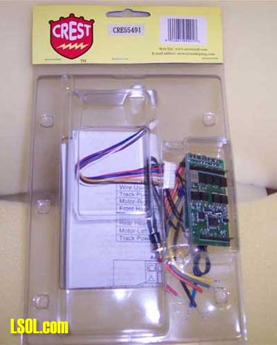
What do you get? Our sample unit was a transmitter/receiver set (CRE 55492) which includes a 75 Mhz transmitter and an onboard receiver. If you want to control sound features you will also need to get an accessory controller (CRE 55495).
The transmitter and receiver come packaged in a clear plastic blister pack
The transmitter measures 6 1/2" x 2 1/2" x 1" (not including the clip) and the antenna extends to 40". The transmitter's batteries are installed from the rear of the unit.
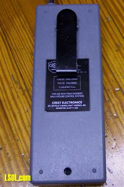
You have to remove two Phillips screws to take off the back of the transmitter
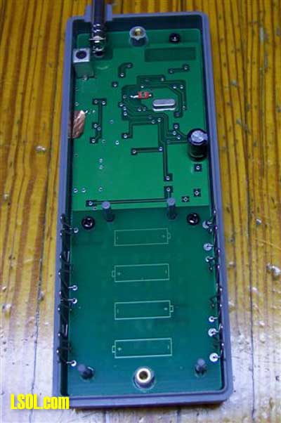
to reveal where 4 AA batteries are installed. The transmitter has a spring loaded belt clip
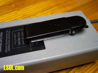
on the back so you can hook the unit to your belt or pants. The front of the unit
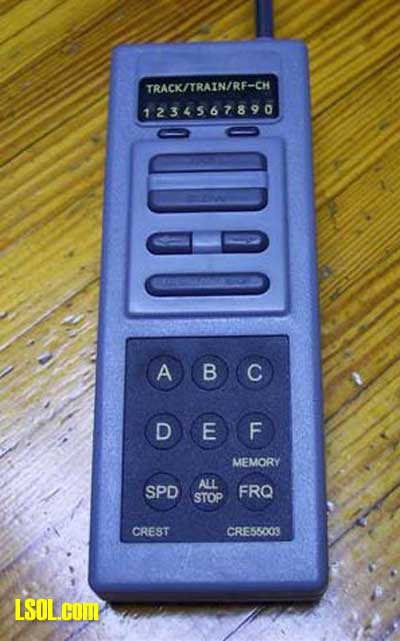
has 10 indicator lights, which are used to indicate the channel you are controlling. The channel is selected with two buttons just below the indicator lights. Below that are two wide buttons for "fast" and "slow" (speed up/slow down), then two direction buttons. Just below them is another wide button labeled "emergency stop". The bottom half of the transmitter has 6 round pushbuttons labeled A-F, and buttons for selecting the frequency, displaying the speed, and an "all stop" button that will transmit an emergency stop signal on all 10 channels.
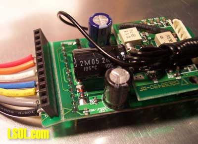
The receiver/controller measures 2 1/4" x 1 5/16" x 1 1/4"

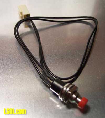
There is a small two-wire plug for the programming button
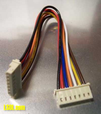
and a larger multi-wire plug, which is used with the optional accessory controller board connector.
On the bottom of the circuit board is a group of pins sticking out
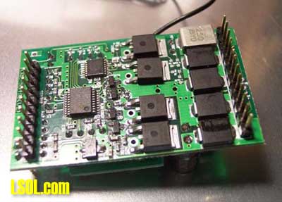
which is to be plugged into a socket on the newer Aristocrat locomotives to switch them over to onboard control. If your intended locomotive does not have this you will need to use the adapter socket
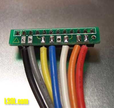
which has a number of short wires terminating in bare ends to wire into your locomotive. The adapter socket is actually part of the circuit board and is pre-perfed
so it can be snapped
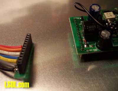
off then you need to plug it onto the pins on the bottom of the control board.
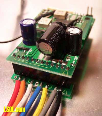
I would have preferred Aristocraft would have just installed a series of screw down terminals on the board instead of this makeshift arrangement as this significantly adds to the thickness of the controller (which can be a factor in tight installs) and the short leads from the adapter need to be either soldered and shrink wrapped (or taped) or you will need to install a terminal strip to connect to your locomotives wiring. The receiver also has an antenna lead that is 30" long.
The optional accessory controller measures 2 3/4'" x 1 1/16" x 1/2" and has 5 reed switches
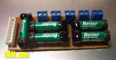
which are for controlling the sound effects and/or lights. Each switch has screw down terminals on the PC board. Switch A and B are momentary contact switches and can be used to control the whistle and bell on a sound card. Switch C, D and E are latching and can be used for turning on and off lights or for sound system effects which require latching. The accessory card is connected to the receiver with a connector cable.
The 6th button "F" turns the front and rear headlights power on and off.
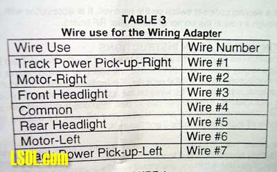
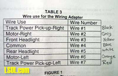
All the wires from the adapter socket are different colors but the identification chart identifies the wire by number from right to left 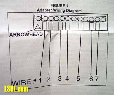
and a number code chart is in the instructions to identify each wire and its respective role in wiring.
One of the first things I did was write each wire's color next to its position on the chart to make it easy to identify which wire was which.
The kit does not include a fuse and one should be installed between the batteries and the receiver for protection.
The instruction manual that came with the kit was rather unclear and was titled "HO Train Engineer Wireless Control System" so it didn't even appear to be the correct manual. Fortunately the programming set up on the HO version of the TE is the same so what was in the manual did work, but the wiring diagram in it was not applicable. There was also a couple of photocopies of wiring instructions included, which were applicable to the 75 Mhz Train Engineer in a large scale application. There are better instructions on Aristocraft's website which you will find useful.
The Aristocraft TE unit is compatible with any sound card on the market; however, you will need to install an opto-isolator if you are using the TE with a Sierra sound card (look for the article about making your own opto-isolator circuit board right here on LSOL.com)
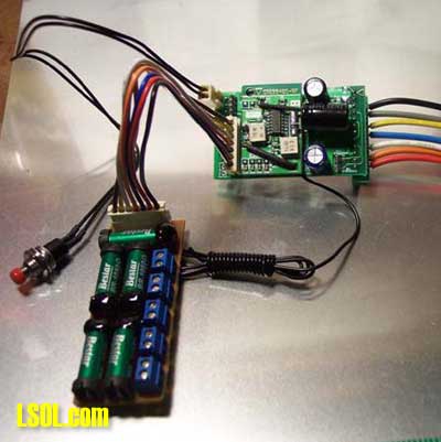
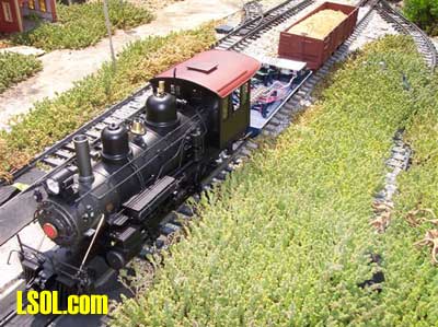
Testing the unit Just like our other evaluations we tested the Aristocraft TE on a test bed using a Bachmann 10th anniversary 10 wheeler with a spare tender and an auxiliary battery car.
Hooking It Up
Because the TE receiver just has wire leads coming out of it I used a terminal strip to wire it up on the test bed.
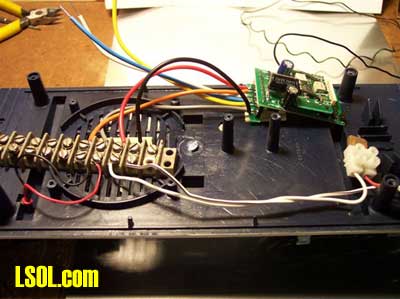
I connected the black and red wires from the receiver to the input from the battery (the polarity does not matter). And the Grey and Orange wires got connected to the motor leads. There are also wires for the front headlight, rear headlight and a common wire. I hooked up a 12v light bulb to the front headlight and common wires, as this light would be needed for programming.
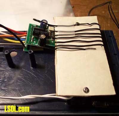
Finally we used that same piece of cardboard we used in the other tests to wrap the antenna lead around
The test unit with the engine, tender and battery car was then taken outside for some test running.
Programming To set up the Aristocraft TE first you need to set up the transmitter. On the transmitter unit press and hold the "FRQ" button for 2 seconds. One of the lights at the top will light up to indicate the current radio frequency. Press the "FRQ" button again until you get to the frequency number you want to use then press any other button or just wait for the light to go out to set the frequency.
Now you need to set the locomotive to the channel you want to use. First use the channel select buttons on the transmitter to get to the desired channel.
Next turn on the power to the receiver and press the code set button (the red push button that plugs onto the receiver). There is also a micro push button switch on the receiver that can be set with a sharp pencil that serves the same purpose. Once you press the button the headlights will start to blink rapidly (this is why we had to hook up the light bulb on our test bed).
Now press and hold a letter button from A-F until the blinking slows. This will set the momentum. "A" will have no momentum and "F" will have maximum momentum. I found that the settings in the higher ranges were very long and made the control of the engine too unresponsive, so I would suggest you use one of the lower settings. After pressing a momentum setting you need to press and hold letter key again until the light stops blinking to set the reversing delay. "A" has a .1 second delay, "B" is .2 seconds, "C" is .5 seconds, "D" is one second, "E" is 1.5 seconds, and "F" is 2 seconds.
Finally press either "A" or "F" to set the momentum feature of the receiver. "A" enables the memory and "F" disables it. What this feature does is make the receiver remember its last setting when its power is restored. The idea behind this is if you are using track power to run your engine this will keep the engine running smoother over dirty track. If you are using battery power you will want to disable this feature.
Evaluation of controls The Aristocraft TE controller uses a momentum throttle. To move forward, push the "fast" button and the train will start to move forward. When it reaches the desired speed let go of the button. To slow the train, hold the "slow" button down. The train will decelerate and stop. For a rapid stop use the "emergency stop button". Direction is controlled with the two direction buttons.
If you press the direction button that is opposite of the direction your engine is traveling the engine will quickly stop, then reverse in the opposite direction, and speed up to the same speed it was traveling before you reversed. The amount of time it takes to stop and reverse is programmable.
The "speed" button will make the lights at the top of the transmitter light up like a bar graph to indicate the speed you are traveling at (more lights lit the faster you are going). The only draw back to this is that the transmitter assumes the receiver has responded to all your signals so you may find the transmitter shows you are traveling at a certain speed level while your engine is in actuality traveling at another if all your command signals were not received.
Range I found that the unit operated to a maximum range of about 30 feet. I also found that the "fast" function did not always work at the same range other functions would. For example I found that from 30' away the "emergency stop" operated reliably and I could get the slow function to respond, but the "fast" not operate very reliably until I got with 5' of the receiver. I also found the reliability to vary greatly, and what worked one time at 30' would not operate until I got ten feet closer the next time.
| Editor Note: There are several messages at the Aristo-Craft site that discuss improving the range of the TE System. The key is the antenna in the engine being stretch to it longest length, or even attaching the antenna wire to the power side pick up of the motor to use the track as an antenna. Also, the TE system can sometimes not respond when the voltage drops below 12 volts. Aristo-Craft recommends a battery cut off device for low battiers. This will help extend the live of your batteries, and avoid a none responsive situation with your engine. |
I had one incident where I tried the "emergency stop" to avoid a collision with another train and my test train would not stop at all. After my engine had derailed and was sitting there with the wheels spinning I continued to press the emergency stop from just a foot away but nothing happened! I ended up turning off the power and resetting it, and then it started responding again. 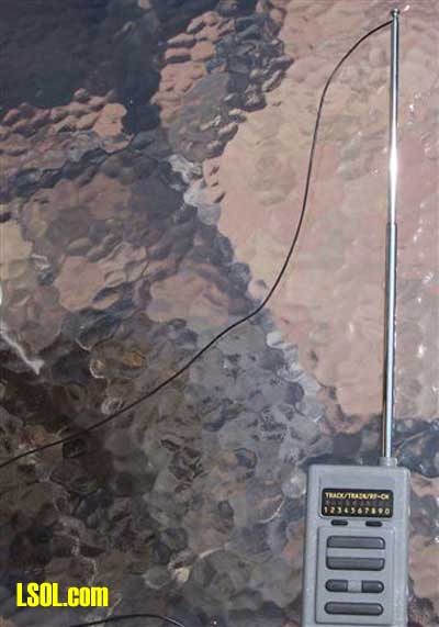
I then tried a trick I had learned about when the 75 Mhz TE first came out and connected a piece of wire to the antenna and this improved the reliability and range somewhat.
Specifications: Input Voltage -------------------------- 12-24 volts
Maximum Current -----5 amps, 3 amps continuous
Contact:
Retail Prices:
On-board 75 Mhz receiver and transmitter (CRE55492) $213.00
On board 75 Mhz receiver only (CRE55491) $130.00
75 Mhz Transmitter (CRE55473) $83.00
Accessory Board (CRE55495) $45.00
Pros:
- One transmitter can control up to 10 locomotives
- Transmitter can be hooked on your pants or belt
- All Stop button on transmitter will halt your entire railroad
- Emergency stop button
- Programmable momentum and reversing delay
- Plug and play compatibility with newer Aristocraft engines
Cons:
- Transmitter is too large to be placed in your shirt pocket
- No screw down connectors for wiring on receiver
- Poorly written instruction manual. Option Technical Guide can be purchased.
- Wiring is not labeled on receiver
- Requires an opto-isolator for use with Sierra sound cards
- Requires an optional accessory board for controlling sound functions
Coming up:
Next we will wrap up with a final side-by-side comparison of all three systems we evaluated. Then we will start a series on some step-by-step installations in various engines. Top of Page