Layouts
Two Trains, One Track
Feb 24, 2012


By Bill Ness |
Author
Bio
One loop on my layout is 175 feet long and is set up to run two trains. The trains are kept separated by small speed changes and I wanted the speed changes to be small enough that they would not be obvious.
|
Dallee Electronics, Inc., has numerous devices for automated signaling and train control. They also show many wiring diagrams on variations of train control, but I didn't see any using the method presented here for two trains on one track loop. The trains are kept separated by speed changes subtle enough that an observer might not know the speeds are being varied.
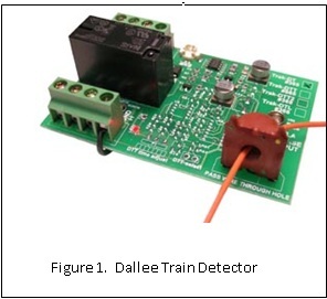
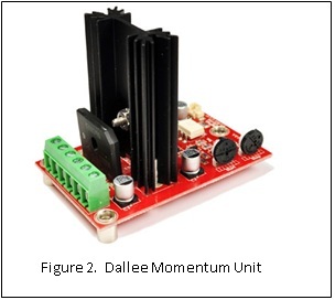
One loop on my layout is 175 feet long and is set up to run two trains. The trains are kept separated by small speed changes, and I wanted the speed changes to be small enough that they would not be obvious. By using a Dallee Train Detector, a Dallee Momentum Unit, and some diodes, this has been achieved. With the kind permission of Dallas Gutacker, Figures 1 and 2 show these units as they appear on the Dallee web site.
 |
 |
I have now ordered from Dallee three times and all orders have come promptly. The items were packaged well with ample padding and were in good shape. I am very pleased with these items and the prompt service, and both work well, The Momentum Unit works in only one direction, which is a limitation. In the other direction, the train runs through the Slowing Block, but at slightly reduced voltage.
Since this is stated clearly on the Dallee web site, I knew it before I ordered. It will work in the other direction if I make some changes to my layout wiring and rail gaps. The relay contacts on the Train Detector are rated at 5 amps. The Momentum Unit is rated at 10 amps DC or 8 amps AC.
I had been thinking of using some big capacitors, an idea I got from one of David Bodnar's many fine articles. In fact I had emailed him and he offered some good suggestions. THANKS, DAVE!! However I decided to try the Dallee Momentum Unit. Since I hadn't seen a diagram of it used like I am using it, I wasn't sure it would work.
My layout runs on conventional track power and the loop being discussed is divided electrically into three blocks: a 40 foot Detection Block, a 49 foot Normal Block, and a 86 foot Slowing Block.
The Mogul in Figure 3 is in the Detection Block, which starts about where the caboose is. When it goes through the bridge, it will enter the Normal Block. The train in Figure 4 has just come down a 2 percent grade in the Normal Block. Once it has gone through the curve, it will enter the Slowing Block and begin climbing a 2 percent grade on it's way to the Detection Block.
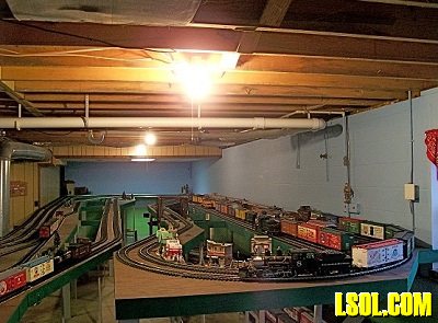 |
FIGURE 3 - In the Detection Block
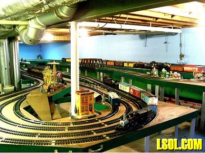 |
Figure 4 - From Normal Block to Slowing Block
Here's a summary of how it works. When neither train is in the Detection Block, both trains run at normal speed. However, when one train is in the Detection Block, the other one will slow while it is in the Slowing Block.
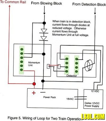
A more detailed description of how it works is that when no train is in the Detection Block, current flows from the Power Pack to the common rail and back to the power pack from the Slowing Block through the Momentum Unit at full voltage, so a train in the Slowing Block runs at normal speed. However, when a train is in the Detection Block, current back to the Power Pack flows through the coil of the Train Detector which energizes a Double Pole Double Throw (DPDT) relay. Two contacts of the DPDT relay then route 12 VDC to the Momentum Unit, which starts gradually reducing voltage to the Slowing Block.
When the voltage has been reduced by 1.4 volts, the diodes limit the voltage reduction so that a train slows but does not stop. When the train leaves the Detection Block, the DPDT relaxes and opens the 12VDC circuit to the Momentum Unit, which gradually restores full power to the Slowing Block. The total speed change is small, and the speed changes are gradual. These speed changes are less than those caused by the curves and grades, which really does mask their existence.
As can be seen in Figure 5, the Train Detector is powered by 12 volts DC, and that power is connected to two terminals of the two DPDT terminal blocks. The Momentum Unit is powered off the Train Detector. There is no provision to power the Momentum Unit other than from the Train Detector. The 12 VDC to the Momentum Unit is through the Common and Normally Open contacts of one pole of the relay.
 |
The Momentum Units are designed to bring a train to a complete stop smoothly and then bring it back to normal speed. Since the Momentum Unit allows trains to run in both directions, and even works on AC, I didn't think using the diodes would damage the unit, but I contacted Dallas Gutacker of Dallee and told him how I am using the Momentum Unit and he replied that it should be just fine. The momentum is adjustable, and since I wanted very gradual speed changes, the unit is set for the slowest speed changes.
If you've read this far and are thinking you might like to try this, here are some comments and observations that might be helpful. I wish I had hard and fast rules, but I can only give comments based on my experience with this one loop of track.
General Comments
1. I know of no reason this will not work with trackside Train Engineer, but I haven't tried it.
2. Only certain combinations of relative train speeds, block lengths, and number of diodes will work. It took a lot of trial and error before I got it working to my satisfaction. Some changes to block length and number of diodes may be necessary on your loop too.
3. I'm a firm believer in soldered wire connections, but before you solder anything make the connections with wire nuts or just twisting the wires together. When you have everything working like you want, then solder. I connected and disconnected a lot of wires, and soldering too soon was a mistake.
4. I have noticed that train speed sometimes changes as the trains warm up. The change is small and would not matter when running only one train. However, in this approach, the trains are being kept separated by small speed changes and so these changes can be important. What you observe in the first few minutes of operation may not be the same as what you observe later. This can affect the operation stabilizing at the beginning of operations.
5. Typical wiring will have one rail with no gaps, and the other with gaps to divide the track into blocks. The Momentum Unit works with the common rail being the positive one, and the rail with gaps the negative one. If the common rail is the outer one, the setup works with trains running clockwise. If the common rail is the inner one, the trains must run counterclockwise.
6. Big capacitors could be used to smooth the speed changes instead of the Dallee Momentum Unit. I am not prepared to comment further on that possibility.
7. The diodes must be rated for the amperage and voltage of the application. At Radio Shack, I found some rated at 6 amps, which is overkill, but they don't cost much, so why not. Voltage ratings are seldom a problem The voltage drop when current flows through a diode can vary, but 0.7 volts is often used for calculations with silicon diodes. It's trial and error anyway. Dallee also has diodes available.
Specific Suggestions
1. It is easiest to get it to work with trains that run at close to the same speed. Test train combinations until you find two that the faster takes 20 or more laps to catch the slower when the trains start with the faster one barely ahead. Or you can put the trains half a lap apart and run them until one catches the other. Find a combination that takes at least 10 laps for one to catch the other. If you do not have two such trains, pick the two with the greatest number of laps before the faster catches the slower.
2. The relative lengths of the blocks are probably more important than the absolute lengths. My Slowing Block is about 49 percent of the total length (86/175=0.49). Similarly, the Detection Block is 40/175, or 23 percent, and the Normal Block is 49/175, or 28 percent.
These percents could be a good starting point in setting up a different loop. For example, in setting up a 120-foot loop, the Slowing Block would be 0.49 x 120 feet, or 59 feet. The Detection and Normal Blocks would be 28 and 33 feet, respectively.
These lengths could vary and still give stabile operation. For example, the Slowing Block could be from 55 to 65 feet and the Detection Block from 26 to 30 feet.
Trains should always go from the Detection Block into a Normal Block, not directly into the Slowing Block. My setup has only one Normal Block, and so trains go from the Slowing Block directly into the Detection Block, but a second Normal Block between the Slowing Block and the Detection Block is fine.
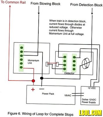
3. Before you work on getting the trains to slow, I recommend wiring the Momentum Unit with no diodes, as in Figure 6. The unit comes with complete instructions that will show exactly which three of the six terminals to use. I used the wiring diagram labeled "DC - Single direction control" in those instructions. The minus (-) output of the power pack is connected to the "R1-DC" terminal. The lead from the Slowing Block is connected to the "S-DC" terminal. The positive (+) lead from the power pack is connected to the "Rail-2" terminal.
Place the two trains with no lighted cars about half a lap apart and try running them for several laps. With no diodes, the trains will come to complete stops in the Slowing Block. The reason for not running any lighted cars is that if a train in not completely in the Slowing Block when the other train enters the Detection Block, the Momentum Unit will have reduced the voltage in the Slowing Block before the entire train is in. When lighted cars bridge the gap, full voltage will be applied to the engine causing it to jerk.
4. At this time, you can start putting diodes in the circuit so that the trains slow but do not stop. The number of diodes can vary. I suggest using two diodes initially, as shown in Figure 5 earlier. If operation stabilizes, you may want to start trying other trains. If the operation is stable for all the trains you want to run on this track, you may not need to make any changes. I have found that with two diodes I can run lighted cabooses and the sudden voltage change does not cause enough jerk to be of concern. More about lighted cars and jerking is discussed later.
Stable Operation
In stable operation, the trains can run indefinitely without one catching the other. It can be very confusing to know what's going on when operation is not stable. So it may be helpful to know that I have found two stable scenarios. In one stable scenario, Train F, the faster one, enters the Slowing Block before Train S, the slower one, enters the Detection Block.
Train F is still in the Slowing Block when Train S exits the Detection Block, so Train F is in the Slowing Block the entire time Train S is in the Detection Block. Therefore, the lap times of Train F are about the same every time around. However, the lap times of the slower Train S vary. Train F enters the Detection Block before Train S enters the Slowing Block, and Train F leaves the Detection Block while Train S is still in the Slowing Block.
So the slow train, Train S, is in the Slowing Block only part of the time the faster Train F is in the Detection Block. When the operation is stable, Train S is at the same point in the Slowing Block every time Train F leaves the Detection Block. If Train F starts catching Train S, it leaves the Detection Block sooner relative to Train S position in the Slowing Block, so the slow train, S, spends less time in the Slowing Block and makes a little faster lap.
Similarly, if Train F starts falling farther behind, Train S spends more time in the Slowing Block. The varying time the slower train is in the Slowing Block is what keeps the trains separated.
In another stable scenario, both trains enter the Slowing Block with the other already in the Detection Block. The lap times of both trains can vary. I have only had this scenario with trains very closely matched in speed.
If operation does not stabilize with two diodes, you may need to add a diode or increase the length of the Slowing Block or the Detection Block.
The time it takes for operation to stabilize can vary greatly, depending on how closely the train speeds match and where they are on the track to start. Sometimes operation stabilizes in three or four laps. I have run for an hour with trains closely matched in speed and operation never stabilized. Because of the close speed match, the separation between trains was only changing an inch or two each time around the loop.
Effect of More Diodes
Figure 5 earlier shows two diodes, and each lowers the voltage in the Slowing Block by 0.7 volts, so that the voltage in my Slowing Block is reduced by 2 x 0.7, or 1.4 volts. Adding a third diode will increase the difference to 3 x 0.7, or 2.1 volts and the trains will slow more. You may have to increase the number of diodes. Longer Slowing and Detection Blocks will require fewer diodes than shorter ones. Trains that vary a lot in speed will require more.
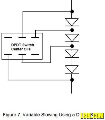
Figure 7 shows four diodes and a DPDT Center OFF switch to vary the number of active diodes. This could make it more convenient to get the setup balanced while the block lengths are being worked out. It could also be made part of the permanent wiring to allow more different train pairs to be run. In the Center OFF position, all four diodes are active. In one of the ON positions, one diode is bypassed leaving three active. In the other ON position, two diodes are bypassed so that only two are active. This diode string and switch would replace the two-diode string in Figure 5.
 |
There are two problems with using more than two diodes. First, the trains will slow more and the speed changes will be more noticeable. Second, the jerk when lighted cars bridge the gap between the Normal Block and the Slowing Block will be greater when a train enters the Slowing Block with the other train already in the Detection Block. Such jerking can shorten the life of the drive mechanism.
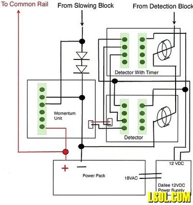
The jerks can be eliminated by adding a TRAK-DTT detector as shown in Figure 8 but only if each train is near or in the Slowing Block when the other one enters the Detection Block. This detector has an adjustable timer and by routing the 12 VDC power to the Momentum Unit through the Normally Closed and Common terminals of it's relay, there is a delay from the time a train enters the Detection Block until the Momentum Unit is activated. When a train enters the Detection Block, the TRAK-DT immediately closes the 12 VDC circuit to the Momentum Unit, but the TRAK-DTT opens that circuit long enough for lighted cars to get past the gap. There may be other ways of delaying the Momentum Unit from reducing the voltage.
 |
Block Lengths
The effective length of the Slowing Block is approximately its measured length minus the wheelbase of the engine. It's only effective when all the engine wheels with electrical pickup are in the block. The effective length of this block is also affected by the momentum settings, which are separately adjustable. The more gradual the deceleration, the less time a train will be in the block. The more gradual the acceleration, the more time it will be in the block.
The effective length of the Detection Block is its measured length (40 feet) plus the length of the train's electrical wheelbase. The electrical wheelbase is the distance from the first wheels with electrical pickup to the last. If there are no lighted cars, typically it will be a foot or two. If there's a lighted caboose, it will be about the length of the train.
Thus the effective length is not necessarily the same for both trains. In some cases it might be possible to get the setup to work by changing the length of the trains, but I have not found it to be helpful. I tried adding a car but the added weight seemed to make the train slower going up grade which nullified any benefit of more length.
I often run two trains about 12 feet long so my Detection Block is effectively 52 feet long for both trains in that case. I also run a 14 foot freight train with lighted caboose and a passenger train with no lighted cars. In that case, the block is 54 feet for one train and about 41 feet for the other.
What Next
It took a lot of trying things to get this to work, but for me it was well worth it. It works better than I expected and I just wish I had done it sooner. The loop is one track of a double track mainline and now I'm eager to get the second one running two trains too. And those unused relay contacts make me think of some block signals. Hmm.
Another thing that's on my list is a tripod for my camera. I'm just not steady enough to hold the camera for time exposures, and that's what's needed to get good pictures in my basement. I put the camera on a 6-foot A ladder to get the shots in this article.
| trains |
| Bill, you are AMAZING !!! |
| carl kokes - 02/24/2012 - 13:42 |
Top of Page
|