Author
Bio
Instead of removing the existing switch and lifting that track, I will leave most of it in place creating an abandoned siding. Well, instead of just having abandoned track I decided that I would put a pair of abandoned boxcars on the track for some added interest. And this decision has lead to my next major scratchbuilding project.
When I started my railroad it was supposed to be for smaller trains, but as time has gone by I have acquired larger trains to run just for fun. And I have since discovered that one of my curves is a bit smaller than most of these larger engines are comfortable with. So I will be redoing that curve, installing a new switch and laying track in a different location.
This has lead to a decision. Instead of removing the existing switch and lifting that track, I will leave most of it in place creating an abandoned siding. Well, instead of just having abandoned track I decided that I would put a pair of abandoned boxcars on the track for some added interest. And this decision has lead to my next major scratchbuilding project.
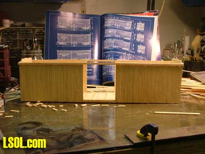
Ok, so I need plans. Well again I turned to the plans that once came inside my Garden Railways magazines. I came up with the plans for a boxcar, plan set #57. I also found an article on the same for a similar boxcar in The 2003 Narrow Gauge Annual issue of Finescale Railroader. The 2 cars come out real close to the same dimensions, so using the GR plans and fine tuning with the FR plans I was set as far as the plans went.
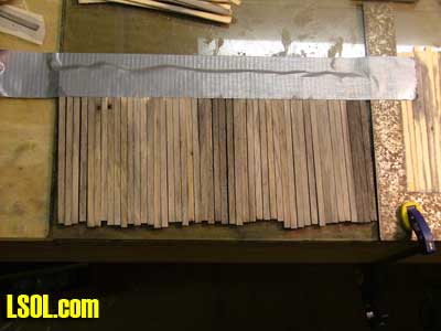
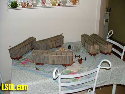
So first things first, I would build a new car to see how its done, then do the sagged ones. Wait a minute. Why do only one new car, if I am going to do one any way, why not do 3? Ok so that's 5 cars, lets make it 6 and "pay back" Bob for his wonderful gift, the leg lamp. But Bob wasn't alone in that gift, I need to make a gift for JD Miller, he was part of that gag too. Ok that's 7 cars, maybe 8...well before I start a new career building 1:24 scale boxcars let me show you what I did.
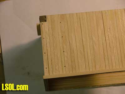
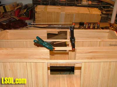
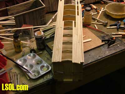
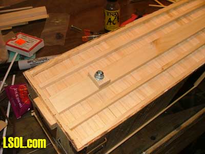
After making all the scale lumber I started with the floors. Putting the floorboards in a square, and using another to keep it all straight I glued on the under floor beams and center sill.
`
I double-checked all measurements as I went and the floors went together rather quickly. But I need 3 sagged floors, how do I sag a floor? First I tried steaming them, but that didn't work. So next I took the 3 floors and put them in the washtub. I put wooden blocks under the ends, and a weight in the center and then did my week's laundry. After the floors had been soaked with a tub full of hot soapy water, then the cold rinse water for 2 loads of laundry they had a definite sag to them. During the assembly I also discovered that they had some degree of twist to them, bonus!
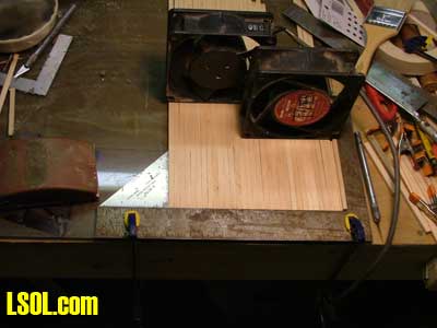
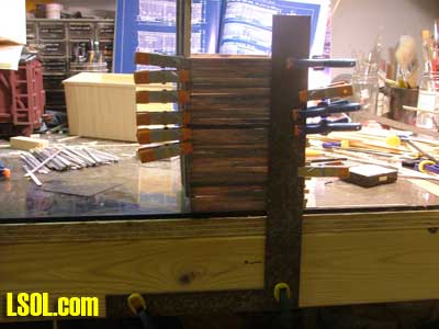
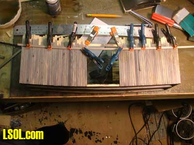
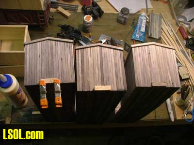
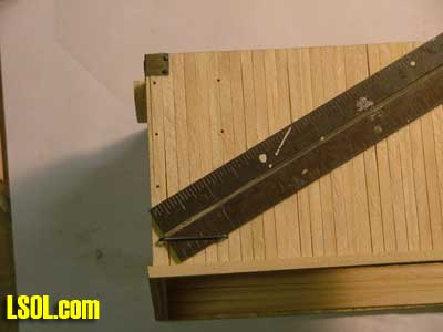
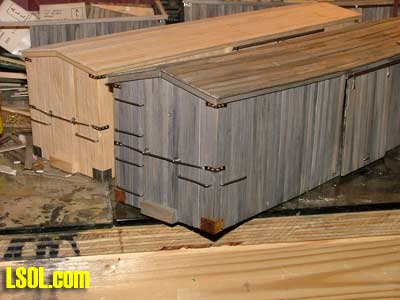
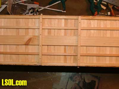
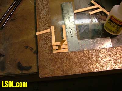
Doing the outside walls on the new cars was easy, lay out the siding boards in the same set up as the floorboards and glue the floor on. First I did the sides, then the ends, so the ends overlap the sides as per the photographs. But on the sagged cars it wasn't going to be that easy, so after playing with some ideas in my head for a while I came up with a solution. For the one side I clamped a board to the edge of the workbench to set the floor on, and then using a square clamped to the workbench I used another square to lay out the siding.
This way the siding stays straight, but also can follow the sag of the car.
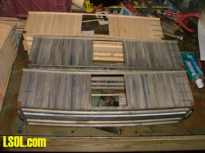
It was suggested to me to just glue the siding on and let it come out as it will. But I have seen several old wooden buildings that had shifted and twisted and the siding always stays pretty much in line, and I wanted that look on my cars.
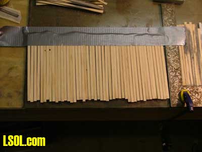
Before I did any assembly of the walls on the sagged cars I took the siding boards and ran a wire wheel over them to distress them. The wire wheel I used is a smaller one mounted in my Dremel tool. I ran the Dremel slightly faster or slower on each batch of boards I did, this distresses each batch a little differently. Then I stained the boards with a mix of about 95% alcohol and 5% black India ink.
I also varied the mix of the stain a bit as I went for a little more variation, and I always stained the boards from the bottom up so the bottom ends would tend to be a bit darker. Also since the wood I used to make my lumber out of was an old shelf there were nail holes in the wood, I saved all my siding boards that had holes in them for the sagged cars, figuring the holes would make good knotholes.
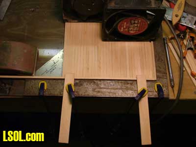
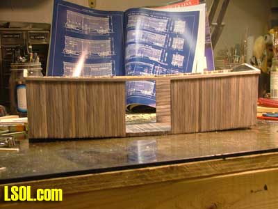
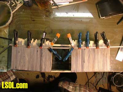
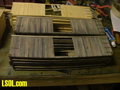
Then unlike the new cars I did the ends next, set the wood in the square, and glued the end of the frame to it, this way the boards I already glued to one side would make sure the end was set at the correct angle to the frame. Then I clamped the square vertical to the edge of the workbench, stood the car on end, and using another square set the siding for the other side of the car.
On all the cars after doing the outside I did the inside of the walls. I did the inside of the ends first, then the sides; this creates a stair-stepped joint that should be stronger then a flat joint. The inside boards are 1/16 x 1/4 laid horizontally, but on the sagged cars again I had to solve another challenge, the floor isn't straight, so the bottom board would not run along the floor.
I made some 1/2 by 1/16 boards, then trimmed them to the curve of the floor. On the sagged cars the inside boards were stained on the side that was to be glued to the outside boards, this way the viewer shouldn't see new wood between the outside sheathing boards. When the insides were done on the sagged cars the inside also got a wash of the stain.
I know that inside a car the weathering would be darkest by the doors, then fade to almost no weathering at the ends. But with the roof on it would be hard to tell if I did it that way anyway, and details that can't be seen aren't worth the effort to me.
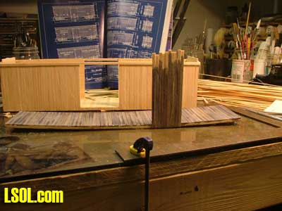
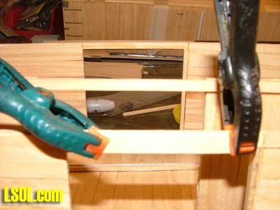
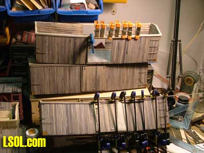
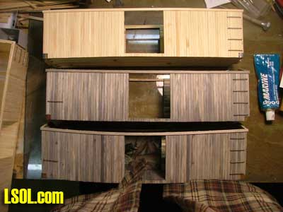
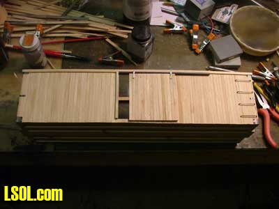
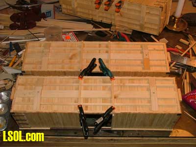
After the car bodies were done I put on the fascia boards, to keep everything straight I temporarily clamped a piece of strip wood across the door opening to keep it the same width at the top as it is at the bottom.
And on the sagged cars I also wire wheeled and stained the fascia boards first. To do the fascia on the sagged cars I measured up from the bottom of the car every 4 or 5 boards and put a mark, that way I could sag the fascia the right amount on the cars, I didn't need to soak the fascia in water. It's thin enough that it would bend, I just needed to use a lot of clamps on it.
Next I installed the end blocks. Again on the sagged cars they got wire wheeled and stained, then glued and clamped into place.
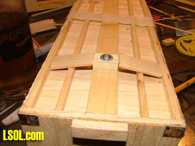
Then I measured in where the truck mounting holes would go. I wanted the couplers to be as close to the end blocks as possible, without hitting them when the trucks swiveled.
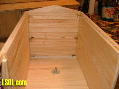
After marking the location of the holes I drilled the holes with a hand drill, so as not to damage the cars. The holes are just big enough to accept the T nuts. Then inside the cars I pressed 6-32 T huts into the holes. The T nuts are what the mounting screws for the trucks will go into when the trucks are mounted.
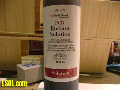
All the steel parts I made for the cars got treated with a photo etch solution. This is available at Radio Shack. The idea was to actually rust the steel parts, but in the end what it did do was to roughen the surface of the metal parts to give the paint a better surface to stick to.
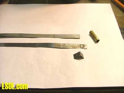
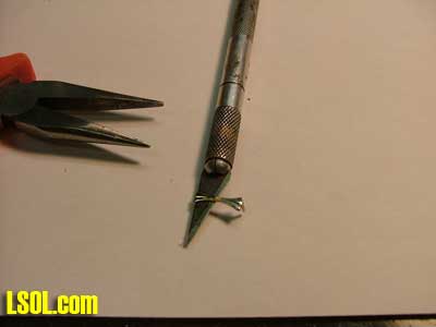
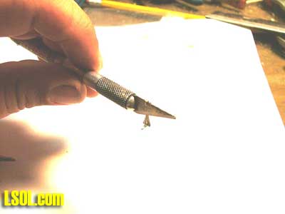
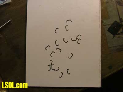
Now for making the corner braces with the polling pockets. I took some thin craft store steel and cut strips the same with as the end blocks. Then I took some brass tubing and stamped the polling pocket into the steel. To do this I measured where I wanted the pocket and drew a pencil line, then I set the steel on a wooden block, held a piece of brass tubing on it and struck it with a tack hammer 2 or 3 times.
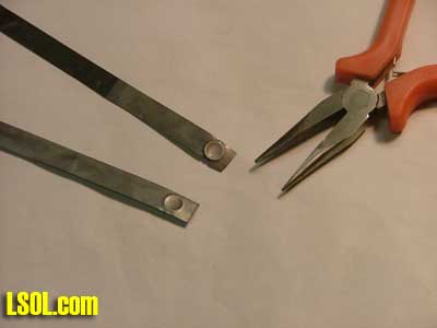
Then I took a pair of needle nose pliers, the type that doesn't have teeth, and flattened the ripples out of the edges of the steel. After that I bent them and cut them to length.
A little trick I learned to cut thin sheet metal. Metal snips will cause it to curl up, so score the metal along the line you want to cut with a knife, and then clamp it in your brake (sheet metal bending tool) and bend it along the score line. You may have to bend it back and forth 2 or 3 times but it will break along the line without curling.
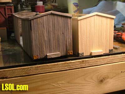
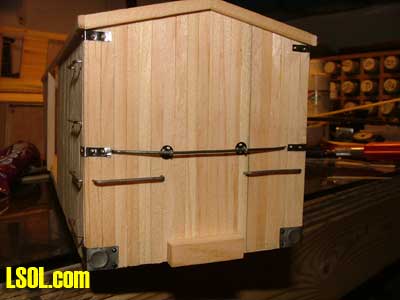
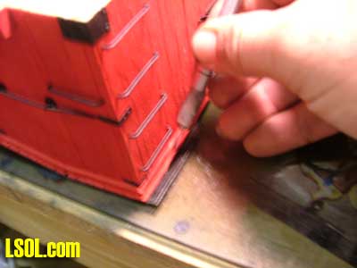
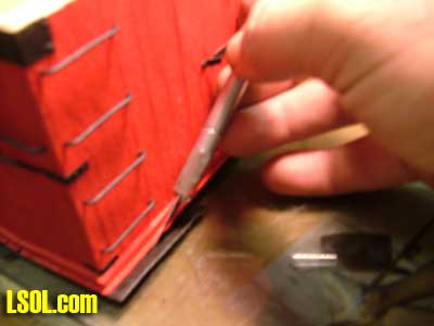
So after making the corner brackets I placed them on the lower corners of the cars and glued them in place with Goop. Then I drilled holes in them in the corners 1/16 inch from each side, and "bolted" them on with HO track nails. The nails on the bottom I cut short so there wouldn't be any sharp points for me to hurt myself on while handling the cars, but the top ones go into the inside of the car and they can't be seen so I left them full length. Of course on the sagged cars I did leave a few "bolts" out and a few others loose.
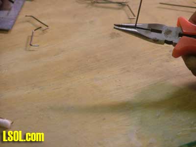
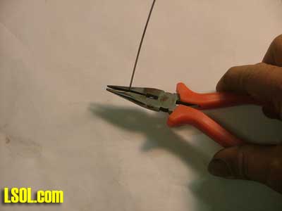
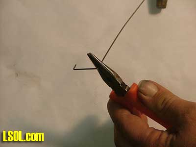
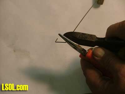
Then came the grab irons, I took some stem wire (florist wire) and bent up the grab irons. First I sanded off the green coating, and then treated the wire with the photo etch solution. Then I held the wire in my needle nose pliers, ones with teeth this time. To get a good working length I always hold the wire in the set of teeth closest to the handles. Then I bent the wire to as close a 90-degree angle as I could.
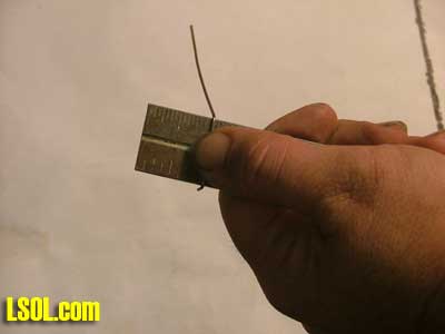
To get the proper length I used a steel ruler and bent them around that.
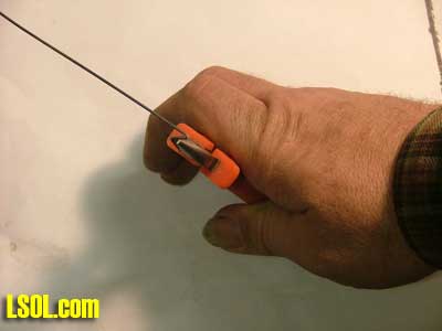
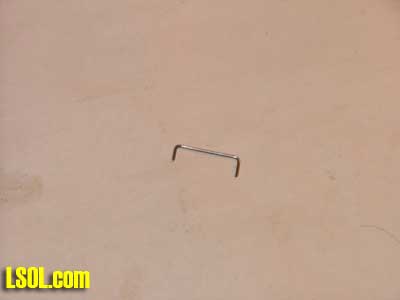
Then holding the grab iron in the same set of teeth in the pliers I cut the wire with my diagonal cutters, as close to the pliers as possible. Simple and quick grab irons.
These cars when first built had only 4 grab irons on the ladder end, so I did that with my "new" cars, less irons to make. I spaced in from the end 1/8 inch, and then I measured and drilled the holes for the irons.
I put some goop in the holes and pressed them into the cars. I used my steel ruler as a spacer to get all the irons sticking out about the same distance.
Then I glued the irons from the inside of the car. On the "old cars I added a few extra grab irons because that is one of the changes that happened to the real cars during their life.
Up till now I had made all the metal parts with steel because I wanted to rust them, I thought real rust would be cool. But the articles I have read must have been wrong because vinegar doesn't rust steel very quickly. So after wasting several nights trying to get the steel to rust I gave up on it. I ended up painting the metal parts with a rust colored paint. Bob Gentile told me about an acid that would do the trick, but the parts were already mounted to the cars, and I didn't want to end up dissolving the cars to get rust.
The corners of these cars also have metal straps on them as reinforcements. So I cut some 1/8th inch wide strips of the craft steel and treated them with the etching solution. Then after I cut them to length, I bent them in the middle, and fastened them to the cars with some goop and craft pins. I didn't need to drill holes in the metal this time because the pins are so sharp (ouch) and small that they can punch right thru the thin metal (and my fingers) with ease.
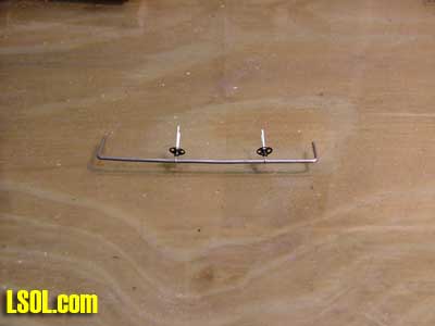
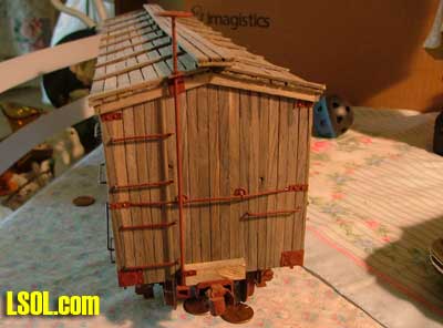
On the car ends is also a rod, similar to a truss rod. So I bent up some more stem wire to make these. For the metal parts that support this away from the car ends I used some small metal sew on snaps. I used the snaps that didn't have the rim on them. I would call them the inside part of the snap, but I am sure a seamstress would tell me that they are called something else. I drilled out the small hole in the nipple of the snap, and bent up some staples I had to hold the support wire to the snap.
Then I measured and drilled holes in the car end and inserted this assembly. Inside the car I bent the rod toward the outside of the car, bent the staples over, then Gooped them in place.
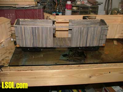
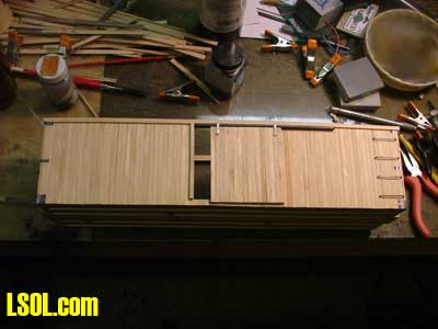
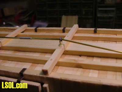
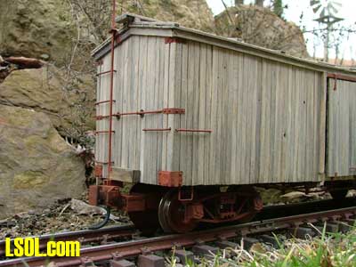
In the one picture you can see the "T" nut and bolt that holds the truck on.
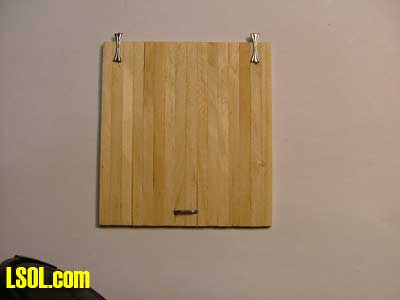
For the doors I just built them in the squares like I did the floors etc. The outside is vertical 3/16-inch boards and the inside is horizontal 1/4 inch boards. For the sagged cars all the lumber was wire wheeled and stained. Once they were cut to the proper height I had to come up with hangers for them.
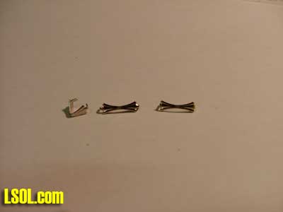
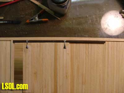
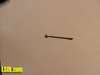
Looking close at the photograph I realized I had seen something very similar on some cheap jewelry that I had seen. So I went off to the craft store and sure enough I found them. But in working with these parts I discovered that they weren't quite long enough to use as I had envisioned. So instead of using half of this detail part, I just used the whole thing. It has some nice detail to it, and for the price I cant beat it.
So I trimmed the tab on one end a little shorter, and re-bent this tab. I bent it so that it was flush with the end of the part, and then bent it again over the back of an Xacto knife blade.
That tab would hang on the door track, the other tab I bent flush with the end of the part, but didn't trim it, that goes into a mounting hole in the door.
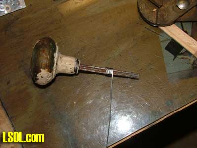
Now for the door handles. I took a piece of 1/4 inch square metal (the shaft of an old doorknob) and bent the florist wire around that. Kind of like making a big square spring.
Then I ran a cut off wheel along opposite sides of the square metal shaft, almost instant handles.
Then I measured and drilled holes in the doors and mounted all the hardware with more Goop
Next came mounting the doors to the cars. I cut a piece of 1/8th x 1/4 strip wood to act as a doorjamb and glued that in place. For the part that the door slides on I bent up some aluminum angle 1/8th inch on each side. These angles I made out of roof flashing aluminum for strength. Then I made some 1/8th square strip wood, and then cut out one corner 1/16th wide and deep in effect making a wooden angle. Then I glued the aluminum angle to the wood angle that I cut.
The wood gives the metal angle something to stick to, and the wood face of the wood angle gives a larger surface to glue this assembly to the car. I don't want this detail falling off, and the door with it. Inside the door openings I glued a board to the rear side of the fascia board to glue this door rail assembly to. I had this board hang down into the door opening 1/8th of an inch.
Then I glued on the door track and hung the doors.
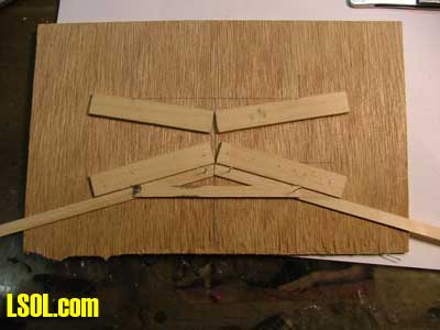
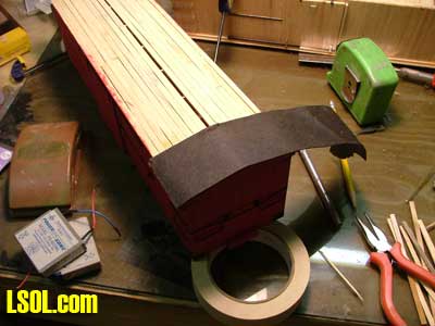
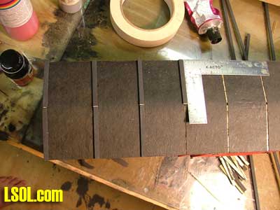
So after mounting the doors it was time to do the roof. Now in the plans it calls for a ridge beam 1/2 inch tall. Now how do I sag a ridge beam that tall, and get the sag to match the floor sag? Simple answer, I don't. So why use a ridge beam at all? Ok, so I made a jig to make the roof trusses, and just used them to support the roof.
In the picture you may notice that the jig has 2 sides to it. Well after making the first car, I changed the pitch of the roof, so I needed to make 2 different sizes of truss. So I don't follow plans all that well. The sub roof is 1/4 x 1/16 same as the inside sheathing. This type of assembly worked out pretty straight for the "new" cars, but on the sagged cars it gets a little uneven and wavy, bonus again.
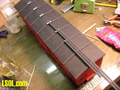
On the new cars I used some black tar paper as the roofing material, held down with more strip wood over the roof trusses.
After the glue dried on each piece I trimmed the tar paper flush with the edged of the roof.
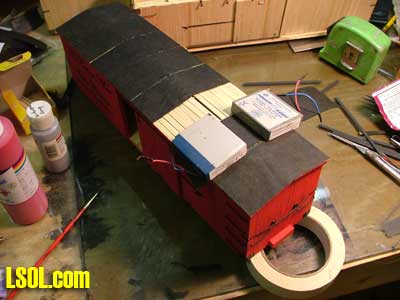
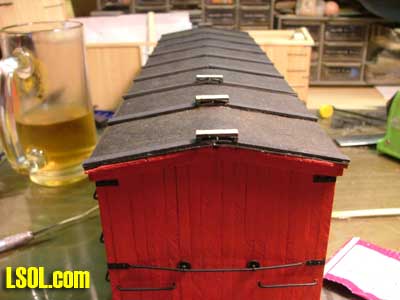
And then I covered the seams with some black painted strip wood.
On the sagged cars I was going to put torn pieces of black construction paper on the roof. But after thinking about how it would look I just left it off. I figured that over the course of how many decades the tarpaper type roofing material would have just completely eroded away. So I put some weathered strip wood on over the trusses like I did on the new cars.
Next I did the under frames of the cars. First I took a block of wood 1/2 x 1/4 and cut it to the same length as the center sills were wide. In these blocks I drilled a hole in the center big enough for a 6-32 screw to pass thru. I then glued these blocks to the center sill using the truck mounting screws to hold them in place while the glue dried.
Then I built up the sides of the bolsters, I used 1/8th x 5/8th wood cut with an angle on both ends so as to be flush with the block and meet the side frame of the car even with the floor.
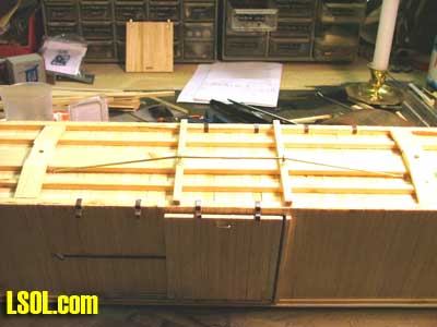
Now I built up the truss rods, first I glued a 3/16 square piece of wood to the underside of the cars. This piece was as long as the car under frames are wide, and positioned under the doorjambs on the sides of the car.
Then I drilled 4 holes in this piece of wood, the outer holes being centered between the long frame members and the inner holes just outside of the center sill.
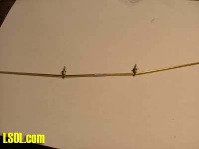
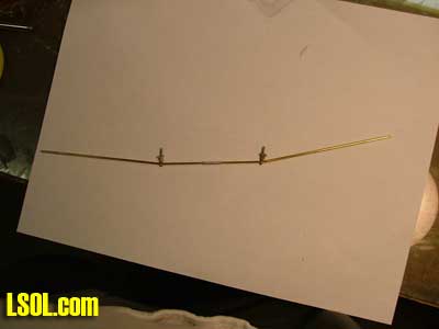
I used florist wire to make eyelets to hold the truss rods, and used 1/8th eyelets to space the rods away from the board.
For the turnbuckles I made them from 1/2 inch lengths of aluminum tubing. For the outer turnbuckles I filed the sides of the tubing till the center opening showed thru so they looked more like turnbuckles. I didn't bother doing this on the inner ones since they will be hard to see under the car.
For the truss rods themselves the outer ones are 2 pieces of 1/16 brass rod, so there is a gap between them to be seen inside of the turnbuckles. The inner truss rods are one-piece rod with the tubing slid over them. The ends of the truss rod assembly are Gooped to the car floors under the ends of the bolsters.
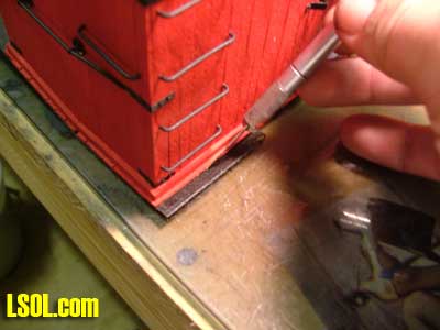
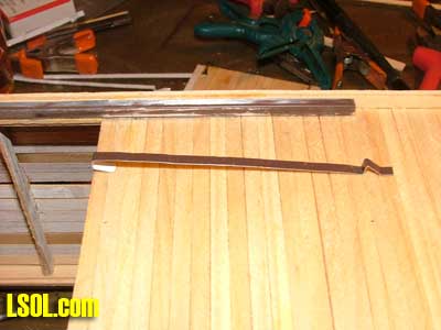
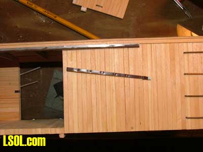
The door slider/stopper assembly on the sides of the cars was then made from a 1/8th inch wide strip of the aluminum flashing material. I made the stopper part by bending the material so there was a 1/8th inch part that lay flat on the car sides, then a 1/4 inch angle part and a 1/8 face that faced the door to be the actual stopper part.
Along the length of this strip I used a nail set every 1/2 inch to put an indentation in the metal to represent the flush bolts they used to secure this on the real cars. The end past the stopper I secured with a brass pin and the other end I bent to go inside the door opening to further secure it to the car.
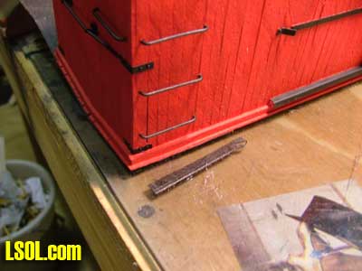
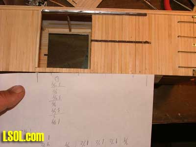
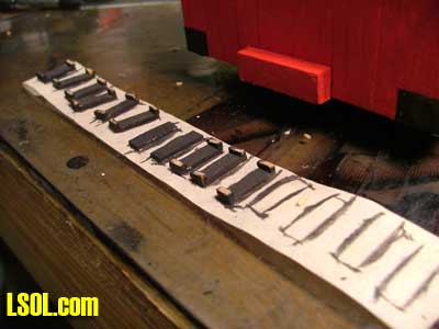
Along the lower edge of the car there are 4 angle pieces used to help guide and secure the door on the car, these I made out of more 1/8th aluminum flashing. I made a series of bends every 1/8th inch to make these, but then discovered that they tended to bind on the door, so the part that the door rides in was made 3/16 to make it easier to slide the doors. For spacing them I drew out a simple guide on a piece of paper and using this I made small pencil marks on the car sides where these brackets go.
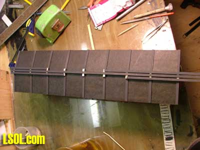
For the roof walks I used the same sized boards as the sheathing (but longer). First I made supports for the roof walk by cutting the strip wood the width of 3 boards plus a little for a gap between the boards. Then on the end of these supports I glued some 1/16th square balsa wood I had left over from my model airplane days. For the new cars I painted these supports black.
I glued these onto the boards that hold down, or did hold down, the roofing material.
Then I glued the roof walk boards to them.
Of course the roof walk boards on the sagged cars were distressed and stained, some were purposely warped, and a few were broken. I really enjoy adding details like that. On the "new" cars I then added a platform above that ladders. I made this out of more strip wood using the squares to hold everything straight. To keep even spacing between the treads I used strip wood as temporary spacers.
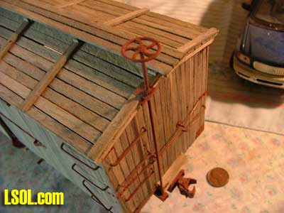
The brake wheels were the next parts to be added, the shaft is 1/16th brass rod. The rod is supported on the ends blocks with a strap made out of a strip of 1/8th steel strip and pinned with the brass pins. The bracket at the roofline was made out of 1/4 inch wide aluminum strip, bent to fit the contours of the fascia and roof overhang.
Where the brake wheel shaft mounts to the bottom of the car I took some rectangular tube Plastruct that I had in my scrap box and drilled a hole in it for the rod. I painted it with the Krylon Ruddy Brown primer and gooped it to the bottom of the car.
I then measured the rod so the brake wheel would be 3/4 of an inch above the roof walks. On the plans the wheel is supposed to be 18 inches above the roof walks and in 1:24 scale that's 3/4 of an inch. The brake wheels are a Grandt line part 3908.
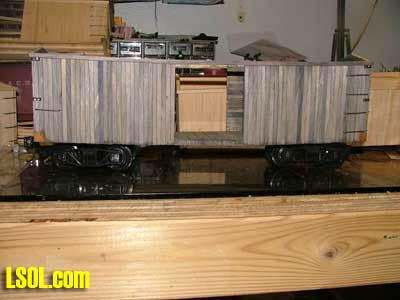
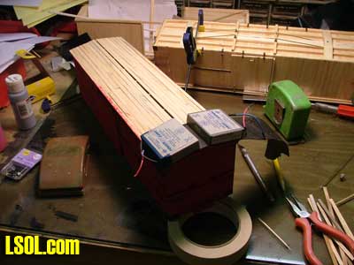
On the display cars I used some left over Bachmann trucks with plastic wheels and some gauge 1 body mount Kadee couplers with the uncoupling pins cut off. For the running cars I used Delton trucks with G gauge Kadee truck mounted couplers and metal wheels.
Of course the whole truck/coupler assembly was painted with Ruddy Brown and an over spray of Ultra Flat Black. To mount the trucks I used the same technique I used on my passenger cars. I took some plastic tubing and made a bushing to go inside the truck bolsters. The plastic bushing is slightly longer than the thickness of the truck bolster.
Then I put a washer on the car's bolster, then the truck with its plastic bushing, then another washer and the 6-32 screw. By making the bushing slightly longer than the truck bolster is thick I can tighten the screws down all they way and the truck will still pivot freely.
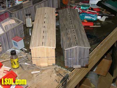
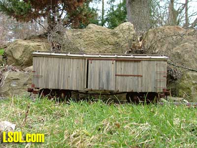
The sagged boxcars are supposed to be well weathered so they didn't get any lettering.
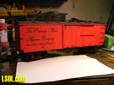
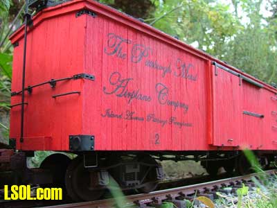
The "new" cars did get lettering and one got some real fancy lettering. You can read about it here.
So now when I finally abandon that siding I have something to abandon on it, plus the Pittsburgh and Castle Shannon Rail Road has 3 new boxcars. And Bob and JD Miller are duly paid back.
I hope that in this article you learned something that will help you on a future project. And I hope that you also learned that a complex project like this is just a matter of solving a series of simple problems and doing a lot of simple steps. Just break down the project into simple steps and you can build almost anything.
Scratch Built Box Cars
Thanks for an excellent article, David. All the photos really help in understanding exactly how you did things. The finished cars really came out nice; they look authentic. I went to your write-up on the lettering and it's great too. I have an unlettered caboose that will probably get lettered now that I know how.
Bill Ness - 09/08/2010 - 07:07
Scratch Built Box Cars
David,
I loved the article. The cars look great. I think I will try one of these this winter.
Thanks for taking the time to build the cars and write the article. The article was clear and easy to follow how you built them. It is nice to know there are still a few of us who actually build things for our railroads.
Thanks, Noel
Noel Widdifield - 09/08/2010 - 14:47
Thanks
Bill, thanks for the comments. Let us know how the lettering comes out, please.
Noel, Thank you too. I revert to scratch-building to get exactly what I want. I am unique and so should my railroad be. My goal with all my articles is to show how a bunch of simple steps can lead to what you want. I really hope that more people give it a try. Scratch-building is fun, and the pride that comes from saying to someone "I made that myself" is a feeling we should all experience.
Noel you do some impressive stuff too, so you know that feeling. ;-)
David A. Maynard - 09/08/2010 - 15:33
GREAT article!
Thanks for the step-by-step article with plenty of pix. You've de-mystified the building of a great piece of rolling stock. I, too, appreciate your taking the time to photograph each step along the way. Looks like I have my winter project all lined out for me!
Dennis Winger - 09/09/2010 - 08:28
boxcars
Terrific looking cars David. Lots of time and patience needed on these but well worth the tremendous effort.
Gary
Gary Condry - 09/12/2010 - 14:40
Patience
Thanks Dennis and Gary
Gary, I am accused of having Patience all the time in my hobbies. That isn't exactly true. I just know when to take a break from something, and some projects I take more breaks with then others ;-)
David A. Maynard - 09/13/2010 - 15:41
Sagged Box Car
David when I grow up I want to model as you do.Fantastic article,very well done. The car you made for me is on my shelf in the train room and I get very good comments on it. I cherish it because I am the type of person who likes things others don't have. It is a very nice model of a box car.Good photo's with the article.
Bob AKA Gatorman
Bob Gentile - 09/14/2010 - 13:24
Thanks
Thanks Uncle Bob. When I grow up I want to be a good a modeler as you are, problem is I also don't want to grow up :D