Scratch & Bash
:
Engines / Rolling Stock
Update your Aristo-Craft SD-45
Jan 9, 2008


By Tom Smith |
Author
Bio
One summer the wires on the connecter between the locomotive and tender broke because of the constant flexing and times when the train derailed.
|
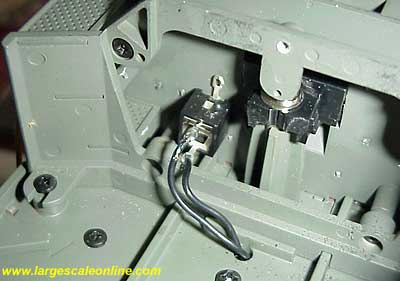
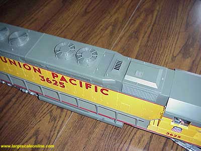
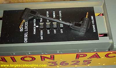
I purchased an Aristo-Craft C16 a couple of years ago. One summer the wires on the connecter between the locomotive and tender broke because of the constant flexing and times when the train derailed and the locomotive tried to pull the train with only the wires. I thought about it and came up with the following modification, which may be of interest. In the rear of the engine near the light switch I installed a 3/32" submini headphone jack. On the tender I installed a 3/32" submini headphone jack. Recently I purchased a pair of the beautiful Aristo-craft SD45's. These locomotives have exceptional detail, and a couple of unsightly MU plugs dangling off the front and rear.
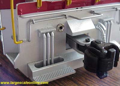
Today I spent less than 1/2 hour each and installed this same system on my SD45's. It really improves the appearance of the locomotive by not having the plugs dangling while not in use. I made a short jumper with two right angle plugs and it stores easily under the cover for the locomotive's electrical switches.
The result is: - A one handed operation to plug the tender in, or the battery car, in the case of the diesels.
- A clean appearance without the dangling plug.
- The plug snaps into place and can swivel which reduces fatigue on the wires.
- If the locomotive and tender, locomotive and battery car, locomotive and locomotive become disconnected the plug pulls out of the socket instead of pulling the connected unit along.
This is how I did it:
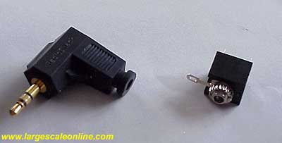
Purchase Radio Shack jacks #274-245, 1 pair per locomotive. Also plugs #274-298, one pair per connector cord needed.
Next cut the MU connectors off as close to the connector as possible to save as much of the original wire as possible. Be somewhat careful, but do not be nervous, there is plenty of wire. This step will make the job easier and as close to foolproof as possible. Strip 1/8th of the wire on the left looking at the end of the locomotive. Leave the other wire until after you solder this one.
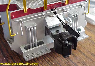
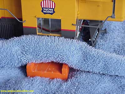
Drill the mounting holes for the jacks. Looking at the photos, you can see that I drilled a hole approximately midway between the coupler cover and the shelf on the left using a 5/32nd drill.
Next lay the locomotive on its top taking great care to protect and support it without damaging any details. Before starting to work on the underside of the SD45, it is important to understand that the weight of the locomotive is going to rest on places not designed for this.
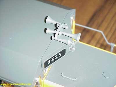
The horns and fan housings need to be protected. To protect the horns, I first pop out the number board housing. On one of my SD45's it does not want to stay in place so I used a small amount of rubber cement to help and at the same time I can easily remove the housing and cement. It is important to be able to remove the number board housing for maintenance.
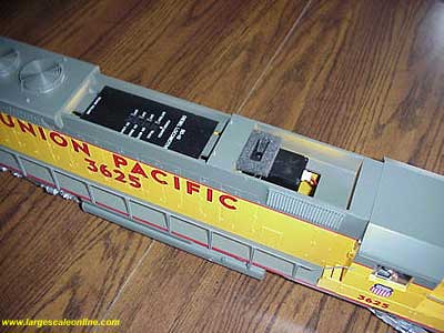
I also remove the smoke unit and control switch covers. The reason for this is they may fall off on their own and I do not want that to happen while handling this heavy locomotive. Be aware that any smoke fluid in this unit will spill when it is turned upside down. The fluid could be hot if it has had very recent use. Smoke fluid works well as a cleaning fluid and may "clean" things you might want left as is. Like decals or even possibly the finish on the surface you are working on. It can also cause a skin rash if your clothing gets soaked and is left on.
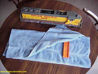
To protect the locomotive while it is on its top, I use a terrycloth bath towel. To protect myself from my wife, I use an old one that is dark colored. I fold the towel in half twice and under the top layer I place a block of approximately 3/4" thickness. In this case a plastic miter saw guide block. It might be good not to be metal or have sharp edges.
Then, very carefully, I turn the locomotive over and gently rest it on its top with the cab on the now covered block. In this photo notice the space for the horns and number boards.
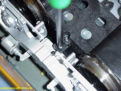
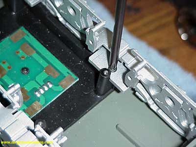
There are four screws for the drive blocks. You will see 8 screws in the drive block and if you look a little harder you will see four more that hold the side frames on. This photo identifies the correct screw and it will be in 3 corresponding locations on each drive block. Remove the screws and you are ready to remove the drive block. There are no wires to disconnect.
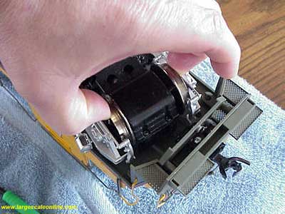
You will find the axles pivot and move side to side, it is not broken, they are supposed to move. Grasp one of the end axles as shown in photo and gently pull the wheels out of the brake shoes. You will notice the side frames are slightly shorter than the wheelbase of the drive block. However, the brake shoes will flex to allow the wheels to slip out.
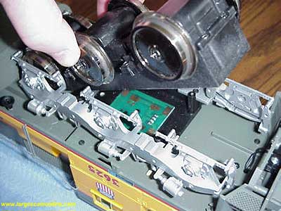

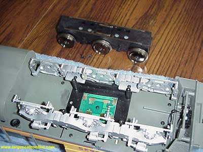
The center wheels will slip out more easily as you rotate the drive block up and out. Being careful not to damage the electrical contacts on the top side of the drive block, you can grasp the drive block as in the photos and with the other hand giving support to the side frames (the one I was holding the camera with) you can work the last axle out. Set the drive block aside with the electrical connections up so they do not become damaged.
Take note, the newer drive blocks have a short boss (button) that mates with a hole in the mounting plate. These drive blocks must be reinstalled in the proper front to rear orientation. The older blocks and mounting plates do not have these features. The old blocks fit the new or old locomotives without a problem. For the new blocks to fit the old locomotive mounting plates either the boss will have to be removed or a hole will have to be drilled in the mounting plate. If you choose the hole option be aware it will have to be precisely positioned.
Now the side frames. I tried removing them before removing the block and installing them after the block. It did not seem to work well. In fact to reinstall the frames I had to again remove the block and start over. So, back out the screws and leave them threaded into the slot in the side frame, doing this will make the assembly easier. Not to worry if you remove them entirely, it will not be a disaster.
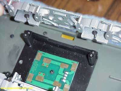
This photo shows the notches in the side frame. To re-assemble simply place the notches against the posts and replace the screws. The reassembly is a reverse of the disassembly and the entire process is much simpler than the amount of words describing it.
Now use a 1/4" drill and turning it BY HAND, remove enough material from the inside of the mounting that the jack can be inserted sufficiently to start the retaining nut. Make sure the jack fits to your satisfaction.
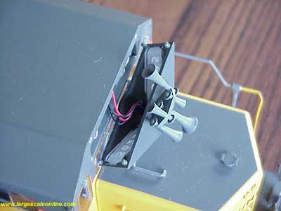
Next solder the wire that has been stripped to the rear tab that is on the same side as the ground tab. The ground tab is the one that is on the post where the plug is inserted. Now strip about 1/8th from the other wire that you left when you cut the MU connector off. Solder it to the other tab in back of the jack. Place a drop or two of the glue of your choice around the base of the threaded post on the jack and push it into the 5/32" drilled hole. Start the nut and snug it down. Replace the side frames taking care to position them properly. Replace the motor block and tighten the screws. Do the same to the other end.
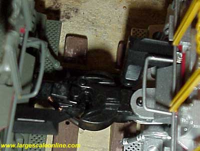
Next make up the connector cable. Note the plugs have been installed at right angles. These plugs are very easy to work with, just be sure to place the o-rings that keep the case closed on the wire before attaching the plug. It is impossible to push the plug through the o-ring.
After installing one plug, place them in the jacks of the two connecting units to determine the cord length. Too short and it will interfere with the couplers and too long could rub on switches. Feed the excess wire back through the locomotive floor and check for side frame clearance. Gently bend the jack tabs as necessary being careful not to have them making contact when you are finished. Notice that some of the pictures show #1 scale Kadee couplers and some show Aristo-craft couplers. That way you can see how each look. Also notice they couple together.
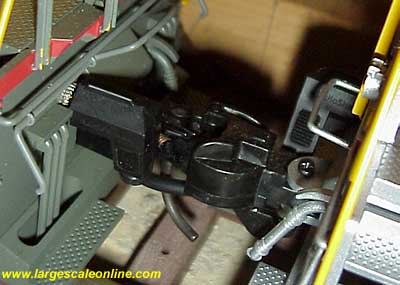
A side note, I have found the #1787 Kadee coupler box with the #1840 reverse offset coupler fit the SD45 very nice. I trim the coupler post to the coupler hood height and cut the coupler box shaft off behind the large pocket. Then I drill a 1/8" hole through the pocket and open the hole in the post for a #4 screw 3/4" deep. This fits better than the combination in these photos and is the exact proper height when installed.
| Connector Cable |
| Tom, Good idea to use the headphone jacks as the basis for connector cables. Task looks easy enough that even I should be able to do it. Might want to mention that folks need to be aware of not reversing polarity between the two units being connected in this manner. Same would hold true when applying this modification to a locomotive/tender conbination. Thanks for taking the time to share this information. |
| Jon D. Miller - 01/09/2008 - 06:22 |
| Cable |
| Great idea Tom. I'm for any project that can be purchased locally. I am, however, curious about one thing. What is the amperage rating of these jacks? Thanks for a great article. Phil. |
| Phil Benedict - 01/10/2008 - 10:10 |
Top of Page
|


