Scratch & Bash
:
Engines / Rolling Stock
Scratch Built A Cattle Car
Aug 22, 2007


By Kirke Fay |
Author
Bio
After a few months of thought on how to approach this, I have compiled a step by step assembly of a generic cattle/stock car using basic scrap wood and "household" Goop with no brads, nails or screws used in constuction.
|
After a few months of thought on how to approach this, I have compiled a step by step assembly of a generic cattle/stock car using basic scrap wood and "household" Goop with no brads, nails or screws used in construction. The wood is just about all Western cedar, cut on a bandsaw, using common sizes in the cutting. All metal fixtures are created from annealed (to soften) copper household wiring. The roof is aluminum flashing and the size is consistant with a short-line railroad. The basic idea is from a set of plans in the Garden Railroad magazine as well as from a 1943 Kalmbach publication featuring builders plans of all types of rolling stock and locomotives plus pictures of different manufacturers of cattle cars in large scale. So here goes !! and I can't believe that after spending 45 years in the printing trade, 14 at National Geographic magazine, 5 at Judd's on Newsweek, and 15 for Doubleday and other popular hardcovers, plus a couple of small stops in a letterpress shop and in film processing that I'm submitting an article!!! Talk about FATE. !!!! 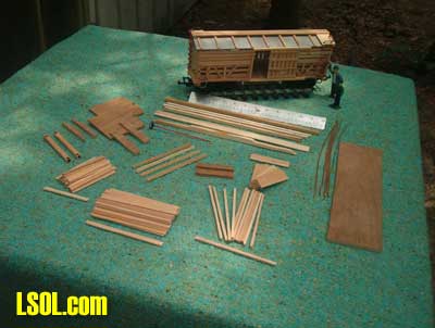
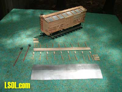
Overview of parts, trimmed out, using a bandsaw for cuts made from a piece of Western cedar, though any wood, pressure-treated pine, or redwood is sufficent. The side beams are 1/8 x 1/8. the door slides are made from routing or cutting into an "L" shape and are 3/16 x 3/16 square, the floor is luan 1/4 inch plywood and is cut to 12 x 3 3/4 high and 3 1/2 wide. End beams are 3 3/4 wide x 7/16 x 1/4 with push pockets burned in with a round tip in a wood burning tool, though a sharp slow drill will also serve. The end planks are 3 1/2 x 5/16 wide with excess trimmed off at the bottom of the carbody and the end beams are fastened beneath the ends of the endplanks with 1/8 overhang protruding. Side planking is spaced and attached on either side of the roof support beams. Note that the lower three planks, inside, serve as rub rails for the livestock. Spacing of the lower three planks are wider than the top four planks on the outside. Side planks are 5 inches long x 1/6 thick. Your choice of roof material is what ever you choose. Planked roof as per Dave Maynard's sway-backed boxcar, or aluminum flashing as my choice, would be two possibilities. The angle of the roof pitch may be copied from any existing boxcar you may have. 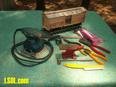 Basic tools and sander used for constuction. The bandsaw is not shown, nor are the various wood clamps.
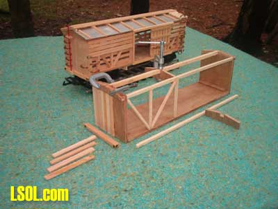 To begin assembly, use adhesive of your choice (mine being "Household Goop"). No nails or brads are used in this project. The notch in the ends as well as the two roof supports is 5/16 x 1/4 Tthis will accomodate the center roof beam which is cut to 5/16 x 1/4 x 12 1/2 inches long, which will be covered at the ends by a scribed piece of luan plywood used as an end sill, cut to 3 3/4 wide x 7/16 high and cut at the same pitch as the end walls and roof supports and fastened to the end wall. The ends in this picture are partially planked with the 3 1/2 x 5/16 cedar, fastened vertical and flush at each side. As a rustic appearence is desired, only light sanding is used throughout the constuction. The first side and roof supports are in place, and the end beams with the push pockets are in place on the underside, showing the protrusion of 1/8 of the beam.  This view illustrates the bracing of the roof supports from the unfinished side.
 In this photograph the end facing the camera has been planked and the beam edge installed beneath and protruding outward leaving a 1/8 lip. Note that an additional upright has been added to the car sides to facilitate fastening the ladders and grab irons on each side, due to the offset planking, inside and outside. A 1/8 x 1/8 strip has been added to the outside edge of the floor to cover the exposed plywood sides. This is repeated at the roof to give the same width on both sides and to install the door slides on. 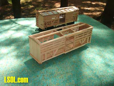 The siding is in place and a dummy floor of rough pressure treated wood is laid to cover the plywood floor, and it is the builders choice to either complete the entire floor or just what may be seen through an open door. Add vertical end boards over either side of the door planking. Install the four "L" shaped door slides on the top and bottom trim boards. These should measure 5 1/2 long, and should be equal spaced at each end to allow the finished door to slide without binding. The door width may vary, depending on the lenth of the car, but in my case works out to 2 1/4 wide. (The finished door is 2 3/4 wide, allowing a 1/4 inch overlap on each side).
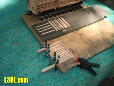 Building the doors. Using 1/8 x 7/16 x 3 inch planks lay them out verticaly as shown, and space out to match the desired door width. Using a series of clamps fasten scrap pieces of wood to a suface to create a jig to hold the door parts while gluing the horizonal cross pieces (4) cut to 1/16 x 1/8, indenting the top and bottom members to act as guides. If when installing the doors into the car slides the fit is snug, sand or file the protruding wood to give space for an easy slide. 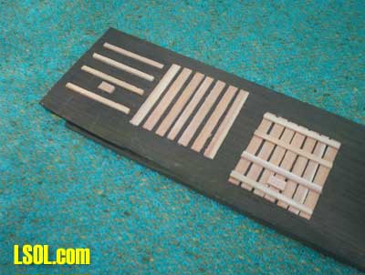 The finished door. (The other door is shown in an exploded position).
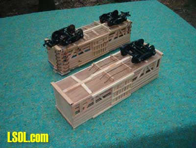 The underside of the car. Note that this is built plain, as nothing can be seen when viewed except the outside truss rods. Cut one 12 1/4 x 1/2 x 5x16 wide center beam. Determine the position of your choice of the trucks, (mine is Aristo-Craft #89101) and cutting in from the ends, cut the thickness back to 1/4 inch, to allow room for the wheels to pivot without touching the car floor. I left a hump in the center section of the beam for additional support and to avoid warping if it should occur. If desired, add angled floor braces from the center beam to the outside of the car floor at the truck bolster. Cut four truss rod supports 1 1/2 inches wide x 1/8 thick x 7/16 high. Position these so that the truss rods running into the bottom of the floor do not interfere with the pivoting of the truck. Space the supports, on either side of the center beam, to align with the door frame openings. Drill eight holes to accomodate the ends of the truss rods, which should be long enough to protrude through the floor and be crimped over inside. I used florist wire that is fairly thick and soft, so it's easy to bend. Notches should be cut in the support beams for each truss rod. A spot of glue where the wire goes through the floor will assure proper fastening.
 Constructing the roof, catwalk, roof ribs and brakewheel. The brakewheel is a Lionel "G" gauge part, but any brakewheel may be used. In my case, I needed a method of attaching it to the central brake rod, and did this by using the extension spray tip off a WD 40 can, with a piece of 1/32 copper wire stuck in the end, and drilled a 1/16th hole in the brakewheel and glued them together. The roof is a piece of aluminum flashing, cut to allow 1/32 overhang on all four sides. This is then scored lightly in the middle, lenthwise, and gently bent to conform to the same angle as the pitch of the roof. The roof is then fastened to the top of the car using a liberal amount of Goop, weighted down if needed or clamped if you have large clamps, and allowed to dry well. Three pieces of cedar strip wood are used for the catwalk and have a slight space between them. Beneath them are 9 supports (refer to the picture) and attached to them are the roof ribs cut square to 1/8 x 1/8 x 1 3/4 which you may extend over the sides slightly and sand them to be flush when dried. The number of roof ribs is left to the builder, I just came up with 9 as an evenly spaced number. On each end of the car above the ladder ends should be a wood platform butting up to the catwalk and extending to the end and sides. 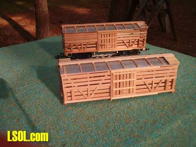 The finished roof installed.
 Annealing the copper wire. This is done to soften the copper to make it easy to bend. The wire in it's entirety is heated red hot and allowed to cool to room temperature without using water to speed up the process. A pair of plyers does really come in handy at this point as copper conducts heat very well as well as electical current. When hammering the copper flat to make the various grabs, ladders and so on, you will find that the copper will curve, and gentle tapping on the side as well as hand pressure will keep it straight to work with. The hammering will also tend to stiffen the copper back up, which will be in your favor when making sharp bends. Refer to next picture which will show all the metalwork required. Pliers and a medium sized hammer are the principle tools as well as a smooth surface of iron or heavy steel. The large electricans pliers was used to determine the width of the ladder rungs when bending. Note that the brakewheel is installed by attaching a small upper platform with a 3/32 hole drilled through it and a small block of woof on the beam at the bottom to set the end of the brake rod into. 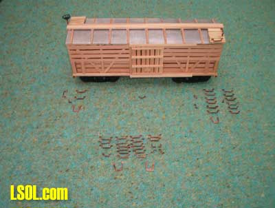 Ladder rungs, grab irons, corner braces, door handles and door stops all ready to install. I used Goop, and just picked off any excess after it dried. 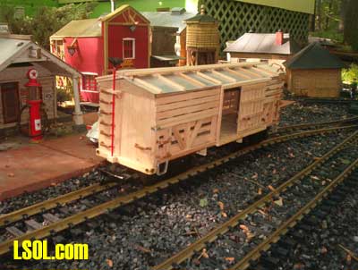 Top of Page
|


