Editors Note: The best part of LSOL.com is all the talent that we have here at our site. If you remember in Part One I saw an idea from Dick McMurdie about a Battery Powered Eggliner. Was in the middle of creating the how-to article when long time member Dennis Cherry voluteered to create the step-by-step instructions, and man did he do a good job!
The Eggliner is a good candidate for converting to battery power and still maintaining track power. This can be accomplished by installing a small toggle switch mounted under the Eggliner. There is plenty of space inside the shell to put enough battery to run the Eggliner for a long time.
Please read these instructions thoroughly before starting this project, it is not a hard project to do and once you are familiar with the conversion It should take about 1-2 hours to compete this project.
Going to a local electronics store, I found all the pieces needed to convert the Eggliner. What is needed:
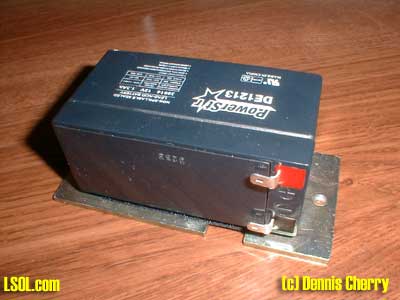
- 12 Volt 1.3AH Battery U1213 gel cell or equivalent. Other battery types can be used, but the 1213 size is the best fit.
- Battery charger: mine is a wall mount rates 12 volts @ 1 amp. It has dual LED's showing the charge and charge is complete.
- 2.1 millimeter Jack and Plug. The jack must be a panel mount type.
- Panel mount DPDT miniature switch
- Velcro (2" x 3" square)
- 2 terminal lugs that fit the battery terminals.
- 22 gauge stranded wire both RED and BLACK (about 2 feet of each).
- 6 feet of 2-conductor cable with 22 gauge wire for the battery charger. Omit if charger already has a cable.
- Tubing to cover the soldered connections on the Jack and switch.
Already have an Eggliner? Dennis will install your parts for $20.00 or supply all parts and install for $59.95 plus shipping. He will take check or PayPal. He can also install our LSOL Complete Eggliner Kit.
Tools needed:
- Needle nose pliers
- Wire cutters small
- Wire stripper for 22 gauge wire
- Soldering iron
- Rosin core solder. (Do not use acid core or solid solder).
- Small drill
- Small bench vise
- Drill bits (sizes I used are 1/16", 1/8", and 5/16" to drill the holes for the switch and Charger Jack).
- Dremel tool with cutoff wheel or a razor saw.
- Phillips screwdrivers.
- Exacto Knife
Therefore, lets get busy and start the conversion.
The Eggliner will run at a respectable speed using a 12-volt battery. I did some current tests to get an idea of battery usage. The Aristo motor block at 12 volts consumes about 200 ma (.2 amps) just free running, placed on track the current consumption goes up to around 300 ma. (.3 amps). Inside the shell Aristo uses 6 incandescent lamps wired in parallel, applying 12 volts to these lamps makes them bright and consumes 300 ma. of current. With these figures in mind, the incandescent lamps consume the same amount of current as the motor block.
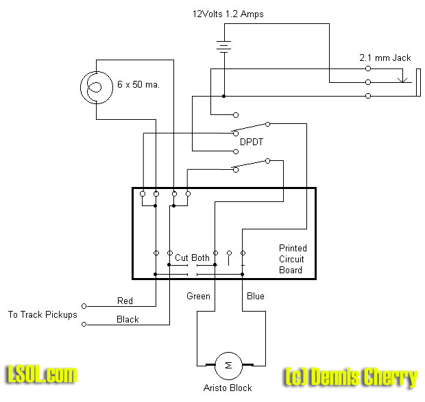
Thus if I wanted to run the Eggliner on battery power with the marker lamps on, I would only get approximately two hours of run time on a 1.2 amp hour battery. Without the lamps about 4 hours. So my design opted to not have the lamps on with battery power but only on with track power. The wiring diagram shows this.
Click for printable picture
One item I need to emphasize is keeping the removed parts separate and secure. It seems Aristo uses several type of screws in this assembly. I have a habit of removing screws or hardware and placing it in a pan in the order I remove the pieces. This way I keep the sizes and amounts of each correct. One suggestion is a shallow baking pan with a piece of terrycloth to fit the bottom. This will prevent the pieces from moving around and combining with other pieces. If you have your own method please use it.
First let's remove the Eggliner shell, Turn the unit over, Aristo uses four Phillip screws, two each located on each side of the Eggliner. I had a problem removing my screws; all four screws had already stripped the threads in my Eggliner shell from the factory. So I went to George Schreyers website and found a recommend fix for stripped plastic holes. Check the screw threads and if you see them full of plastic, then you might need to do the hole repair.
After the screws are removed, you need to carefully remove the Eggliner shell. There are two wires from the lamps in the Eggliner shell soldered to a PC board on top of the Eggliner floor. Unsolder these wires; we will put them back at the finish of the conversion. They are not polarity sensitive, which means it does not make any difference what wire goes on what terminal. Set the Eggliner shell aside for now.
Look at the top of the floor, there will be a large rectangular metal weight with two screws holding it to the floor, remove these screw and metal weight.
Turn the unit over so the Aristo motor block is up, locate the two screws mounting the motor block to the floor and remove these screws. Pull the motor block up slightly and you will see two small connectors, carefully disconnect these to separate the motor block from the floor. You should notice at this time that one connector has two pins and the other has three pins, you cannot reconnect these wrong. Set the Motor block aside, we do not have to modify anything on the motor block.
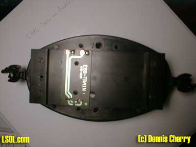
Now what you should have left is just the Eggliner floor assembly with a PC board mounted on the top. Look at the PC board and you will see two copper conductors going between the two connectors. We need to cut these two conductors. 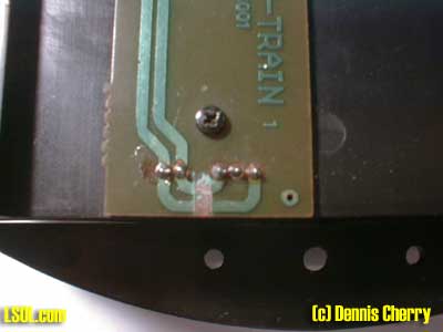
The preferred way is to take an Exacto knife and cut through each copper conductor twice, with a space about 1/8 inch between each cut. Then take your soldering iron and place the tip on the 1/8 inch piece until it gets hot and the glue holding the copper to the board comes loose, you might have to wiggle the soldering iron a little to achieve this. If you want you can just cut the copper then try to peel off the 1/8 inch piece. I do not like to just cut a small section out just the width of the blade, many times you will miss a small piece of cooper and it will give you grief trying to figure out why things are not working right. Been there, done that, more than once until I learned better.
Now we need to drill holes for the Switch and Battery-charging jack. If you look at the mounting tabs on the floor for the Eggliner shell, you will notice a 1/4" diameter mold ejection mark located in the center of each mounting tab between the two screw holes. Take a small punch or a nail and make a small indention in the center of the injection mold mark. Now drill out both holes using a 1/16" drill bit. Making a small hole first in plastic helps prevent a larger drill bit from wandering off and giving you a hole in the wrong spot.
On the mounting tab located on the side where the incandescent lamps are soldered, drill out this hole for the 2.1 mm jack and test fit the jack in the hole.
On the other mounting tab, drill out for the DPDT switch and test fit the switch.
Let's prep some wires to connect to the switch and jack.
Cut 2 each RED and BLACK wires 2 1/2" long.
Cut 1 each RED and BLACK wires 3 1/2" long.
Cut 1 each RED and BLACK wires 4" long.
Cut 9 pieces of insulating tubing 5/8" long.
Take all the wires and on one end strip off 3/16' of the insulation Tin the wires with solder. By doing this step makes soldering the wires to the switch and jack easier.
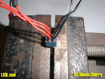
Place the switch in a small bench vice with the terminals facing up. Wiring the switch in a vise will give you better control of the soldering. This will also prevent the soldering iron from touching the plastic floor body.
On the center two terminals solder a RED and BLACK 2 1/2" set of wires.
On the left two terminals, solder the other 2 1/2" RED and Black set of wires.
On the right two terminals solder the 4 long set of wires.
Now inspect that all the RED wires are one side of the switch and the BLACK wires are on the other side of the switch.
Place a piece of 5/8" long insulating tubing on each wire and push over the solder joints.
Mount the switch in the hole drilled for the switch and position it so the short wires are on the left side nearest the PC board connections for the two motor block plugs. Secure the switch to the floor using only the nut provided with the switch. Leave off any other mounting hardware that came with the switch.
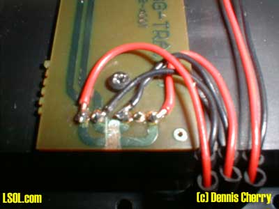
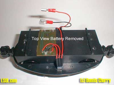
Let's solder some wires to the PC board, Take the center pair of RED and BLACK wires and strip 3/16" of insulation then tin these wires. Form a slight bend out of the tined end of each wire large enough to start fitting around the connector solder joints. Solder the two wires as shown in the picture to the three-pin connector.
SWITCH TO PC BOARD
Take the two left side wires (2 1/2" long) and solder them to the PC Board two-pin connector. Watch the color polarity and check that all connections are good and no solder or wire shorts are present.
Mount the battery charge jack to the floor. My jack is wired for the center pin being the negative terminal for the charger, if you want you can reverse the colors if your charger has a positive center pin.
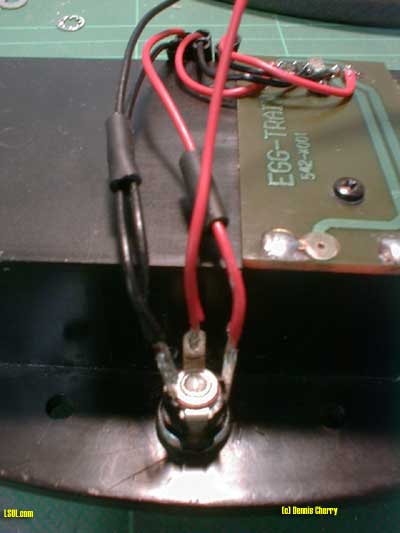
Take the 3 1/2" BLACK wire and one piece of tubing, place the loose black wire next to the remaining BLACK wire from the switch and slide a piece of cut tubing over both wires. Solder these two wires to the center terminal of the JACK and slide the tubing over the connection.
Take the RED wire from the switch and slide a piece of tubing on the wire, solder this wire to the right side terminal. Slide the tubing over the terminal.
Take the remaining 3 1/2" RED wire and solder it to the middle terminal, then slide on the last piece of tubing over the terminal.
The loose ends of the 3 1/2" RED and BLACK wires need to be stripped 1/4", do not tin these wires. Slide a battery terminal on each wire then crimp them tight using a standard set of pliers.
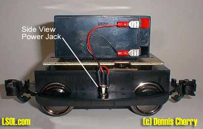
BATTERY MOUNTING
Take the 2" x3" piece of Velcro and place it on the negative side of the battery. Place the other side of the Velcro on top of the piece on the battery and remove the backing tape. Now carefully position the battery on top of the metal weight so the battery and terminals do not protrude beyond the edge of the weight and the terminals are next to the cutout on the weight.
Now mount the weight back onto the EGGLINER floor using the removed screws. Make sure you position the notch in the weight so the solder connections on the PC Board are available for reconnecting the lamps.
Check at this time that the wiring going under the weight is not pinched between the weight and the Eggliner floor. Check that the soldered connections from the switch to the PC Board are not touching the underside of the weight.
Remove the two protective insulators on the battery terminals (if still on the terminals). Connect the RED wire terminal to the positive (RED) terminal and BLACK wire to the negative (BLACK) terminal.
Mount the power block back onto the floor. Be careful here when connecting the two connectors, as they will only go on one way, also check that the wires are not being pinched between the Power Block and Eggliner Floor.
Now you can check the operation of the Eggliner, One side of the switch should start the battery and the other side should run on track power.
EGGLINER Shell:
The cardboard insert on the Eggliner has to be removed for clearance of the battery and two notches have to be cut on the mounting wings for clearance of the battery jack and switch.
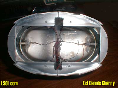
First lets remove the cardboard insert. You will notice this is just taped into the inside shell. Take a pair of needle nose pliers and remove all the tape holding the cardboard insert. You might notice that some paint might come off on the tape as with the Santa Fe Eggliner did. Now rotate the cardboard insert inside the Eggliner then with some effort work the insert out of the shell.
We need to cut a slot on each side of the Eggliner so the Jack and Switch can clear the shell. Look at the mounting tabs where the two pieces join. Make a mark 1/4" on each side of the joint on both sides of the Eggliner. Measure in 1/2" from the inside edge, this should form a box approximately 1/2" x 1/2" on each side. Use a fine tip permanent marker to draw the boxes.
Using a Razor saw or Dremel cutoff disk, cut the sides first then with a Dremel tool make a deep score mark along the back mark, you can use an Exacto knife for this also. Take a conventional pair of pliers and work the piece up and down until it breaks off. Test fit the Eggliner shell onto the Eggliner floor; make any adjustment necessary to clear the Jack and the Switch.
Now you can solder the lamp wires from the shell to the PC Board and then mount the shell to the floor.
You are now finished. Enjoy you conversion.
Top of Page