Power, Sound, R/C
:
Battery
Battery Life Sensor
Jun 17, 2009


By Ray Turner |
Author
Bio
On my battery-powered garden railroad, the batteries always seem to run down at unexpected times, when the train is at the worst possible place - out of sight on the back side of the layout, or in a tunnel, or in the helix. Come see how my solution might become your solution.
|
On my battery-powered garden railroad, the batteries always seem to run down at unexpected times, when the train is at the worst possible place - out of sight on the back side of the layout, or in a tunnel, or in the helix. Then I find myself trying to coax the train -- or pull the train by hand --to a location where I can get at it to change the batteries. All the while it's blocking the mainline holding up trains. 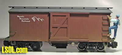 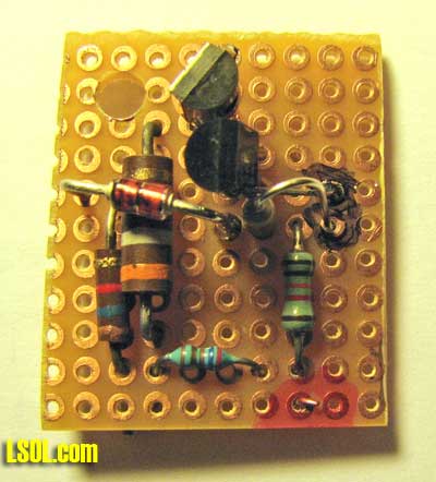
I finally decided to do something about this and finding a bright blue flashing LED in a surplus catalog was just the thing to get me started. I wanted the light to start flashing as the battery started to get weak, but while the battery still had a good 10-15 minutes of charge to run the train. That way, if I didn't see it right away, it would still give me time to stop and change the batteries at a convenient location before the train stopped. 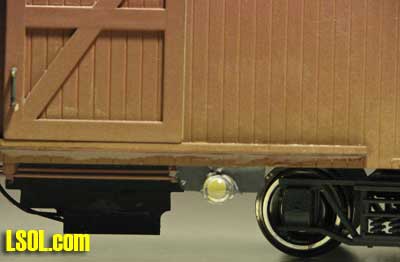 I use a pair of 9.6 volt NiCd or NiMH tool batteries. Nominally, a fully charged battery-pair will deliver 19.2 volts. For reasons I won't go into here, I have a diode in series with the batteries driving all my electronics which drops .7 volts. When newly and fully charged, the voltage to my electronics may measure over 20 volts. It quickly drops to around 18.5 volts in use and stays near that level until it nears the end of its charge. At that point it will decline to 14 volts over a half hour or so with the engines I run. I decided to set the threshold at about 16.5 volts.
How it Works At first I tried to design a simpler circuit with only one transistor, but that "wasted" too much battery current, so I ended up with a two-transistor circuit. Zener diode Z1 turns on transistor Q1 as long as the battery voltage is above 16.5 volts. Q1 then keeps Q2 and the LEDs off. 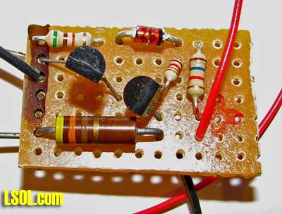 As the voltage to my electronics falls to about 16.3 volts, transistor Q1 turns off and Q2 turns on. This lights the two flashing blue LEDs which are mounted under the tender on each side. Once the LEDs come on, the 24 ohm resistor reduces the voltage to the Zener diode by about .25 volts ensuring that the lights will come on strong and not "waffle" about the threshold voltage. 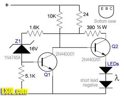 These LEDs have built-in flashers, so they produce a flashing, bright, blue light when turned on. The flashing makes them much more noticeable than ordinary lights. These LEDs operate on 4.5 - 5 volts each at 20-25 ma. The 390 ohm resistor provides the current limiting for the LEDs.
Other Battery Voltages The Zener diode is the threshold determining device. A 16V device was right for my battery voltage. Here is a table for some other popular battery voltages. | Battery voltage | Zener voltage | | 12 | 9.5 - 10 | | 14.4 | 12 | | 18.5 | 16 | | 22 | 19.5 | Finding the Parts It should be noted that Zener diodes have a voltage tolerance of 5% or 10%. You really want to get a 5% unit to get a reliable threshold where you expect it. If you get these surplus, they are cheap enough to buy twice as many as you need and select the ones with the closest value to your needs. I got these, the transistors, and the LEDs from Goldmine
. The resistors can be gotten from Digikey, if you don't find them locally. Semiconductors Q1, Q2: 2N4400/01 - G43375 Z1: 1N4745A - A20411 LED: Bright, flashing - G16424
Construction I built six of these on perforated circuit board. There is nothing critical about component placement. I didn't even try to make them all identical. Here are four of them. 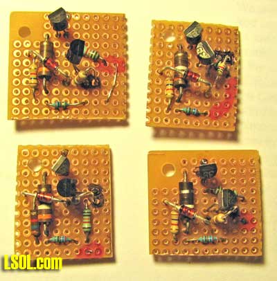 I just located components that connect near each other. I drilled a hole in one corner to mount it. There are four external connections: battery power (2), and the LEDs (2).
Mounting the LEDs and Circuit Board Mount the LEDs to provide good visibility from the normal viewing/operating locations on your railroad. Since my railroad is raised 18-24" in most places, I put them under the tender or battery car. They are pretty unobtrusive here when off, but you may prefer another location. 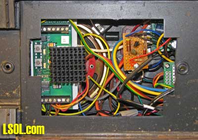 The reason for having two LEDs is that so one can face out each side of the train and I can see it no matter which direction it is going. I used a .25" x .5" piece of scrap Styrene and ground half a round hole in one side to fit the LED, angling the LED up about 20 degrees for better visibility. The LED is glued to the Styrene with Epoxy and the Styrene is glued to the tender with Styrene cement (use Epoxy if Styrene cement won't melt your car's plastic). 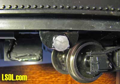 I tried sanding the LED lens on one unit to disperse the light but found that the un-sanded LED was more visible in sunlight. You can find any convenient place to mount the small circuit board. I used a molded-in stand-off on one tender and the speaker mounting boss on another. If need be, drill a hold in the car floor and mount with a self-tapping screw. Be sure to power the battery sensor AFTER the on/off switch on your train so it doesn't draw battery power when the train is turned off. Video of light flashing at YouTube
| Low battery indicator |
| Thank you it's just what I needed. Where did you get the brakeman on the ladder ? I want one. He looks great. Your text and illustrations were very clear. Mike Gruber |
| Mike Gruber - 06/17/2009 - 07:34 |
| Low Battery Indication |
| Ray, A very worthwhile article for those that use battery power. I'll have to construct a few for the NiMH batteries. I also use Crest Li-on. I'm not sure this indicator will work with the Crest Li-on since these have a circuit protection that cuts off battery power. Not sure how much voltage drop takes place before the circuit protection turns off the power. |
| JD Miller - 06/17/2009 - 08:02 |
| Flashing LED low voltage indicator |
| Thanks Ray. I have thought about this from time to time. Anyway, I am going to give it a try and see how it works... |
| Chris Devereaux - 06/17/2009 - 14:09 |
Top of Page
|


