Scratch & Bash
:
Accessories
An Easy to Build Water Column
Nov 7, 2007


By Kirke Fay |
Author
Bio
The basis for this article is that while water tanks were a common sight along railroad lines, in the locomotive servicing area the use of water columns, (or water standpipes) were the norm because from a central water tank, a series of water columns could be installed to service multiple tracks over a wide area.
|
The basis for this article is that while water tanks were a common sight along railroad lines, in the locomotive servicing area the use of water columns, (or water standpipes) were the norm because from a central water tank, a series of water columns could be installed to service multiple tracks over a wide area. Different designs were used, some featuring a cement base with a drain platform, some on a base that did not have a drain but still mounted on to heavy cast iron bases that in turn are fastened to an underlying solid base. The principle of operation being that the tender is situated alongside the column, the fireman or yard worker would open the hatch on the tender, pull the counter-balanced spout over the tender and by a separate control turn on the water by means of either a lever or rope that opened a valve at the top of the column allowing the water to flow into the tender. After use, it was pushed back up and back out of the flow of traffic on the railroads right of way. This model is an "essence" (to quote someone who coined the phase on LSOL, I think) of what from a short distance appears to be a well detailed model, but lacks some parts that would be small and liable to damage and/or collecting grime and rain splatters. Hence, this is a "working" model, or a stationary one, depending on the builder, as there are parts in construction that could be skipped and parts fastened into a frozen position, or as in the illustrated one following that you are going to construct, the spout will pivot, and can be raised and lowered as desired. The central water pipe, which started life as an electrical light conduct with threads at both ends, is 3/8s inch in diameter and for this model is a standard 6 1/2 inches long, though the reader may wish to make it taller, by mounting it on a "concrete" slab with drain, (which will be illustrated as an option) or locate a longer piece of tube at an electrical supply location, or create the same by means of 1/4 inch copper pipe to whatever length is desired. The use of the parts fits this to a scale from 1/29th to 1/20th....using a base of about 3 1/2 inches, will center the column between two tracks diverging from a #4 turnout. So let's begin.
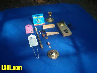
01 - This is an overview of the parts used starting from the left, A child's necklace from a Dollar store/Toy store, cheaply made but having a metal chain, At the top, Going across to the right, A package of Lamp Knobs, of which one will be used at the top of the water column, with a 1/4 inch short wood dowel inserted into its base which will drop into the top of the column, next being an assembled brass candlestick holder (.50 cents) of which the top is unscrewed and a 3/8 inch hole is bored through the existing smaller hole that holds the base and candleholder together. (A base, ready for drilling, is at the bottom of the picture.) If you will zoom in, you will see the brass plated column with a lock nut already in place on it. Coming up from the base, there is, first, the brass nut to hold the entire column upright. Not shown is a round hollow piece of plastic with a 3/8 center hole going through it, that is about a 1/4 inch long (off of a sharpie or large ball point pen), that will cover exposed screw threads between the base and the lock nut that will add that much more to the overall height. Above the brass nut is a 3/8 x 1/2 copper pipe with two 1/16 holes drilled opposite each other at the very top. This is your counterbalance, which will be at the end of your two chains and has the upright column going through it.
Next is a 3/8 brass washer which will be located to hold up the 1/4 inch copper "T" by means of a 1/16 hole drilled through the column and having a short piece of wire passed through it at a distance determined by sliding on the brass washer, the copper "T" and the cabinet fastener which will be at the top of the column. The spout is made from soft wood (pine is fine!!!) and cut 3/4 x 3/4 x 3 1/2 inches. (Two examples are shown, one ready to cut out with pencil markings on it, and one cut out.) Above that is the cabinet door fastener (more on how this gets altered and used coming up), and to the right is two of three possible bases, the first being a 3 1/2 x 3/4 x 6 "cement" base with a drain (which is a plasticville window) and also a base made from leftover ceiling lamp fixtures glued together, which if used with the "cement" base would raise the column about 1 1/4 inches as the column would be attached to the brass base, not the cement (wood) block, the second option being just use the glued together base, and a third option, which is what we are following here, is using the brass candlestick base alone. Yet one more option, is to find a 3 1/2 stamped brass plated base that is used as a ceiling fixture, which will appear the same as the brass candlestick holder, but has a 3/8 hole already drilled in it.
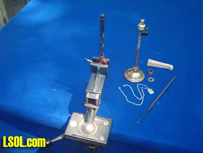
02 - Here the base is pre-assembled, and this step will require patience and an electric drill with a 3/8 inch bit. The copper "T" fitting, which is 1/4 inch copper from a well equipped hardware, must be drilled, slowly, (I recommend quick stops and starts, working from both ends toward the middle.) What we are doing is removing 1/8 from the inside of the 1/4 pipe...this will leave a 1/16 shell, so yes, it will widen out to 3/8 !!!.
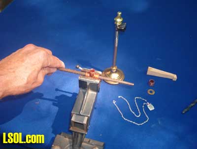
03 - A round file will further enlarge the inside diameter and remove any burrs from drilling. 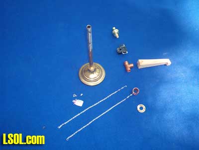
04 - Here is the exploded steps taken so far. It is a must, that the top of the column has the threads ground (or filed) off, maintaining a round but smaller diameter to just below where the hole for the retainer wire is for the brass washer. This in combination with the drilling and filing of the "T" assures an easy rotation of 360 degrees with no binding. The copper 3/8 inch counterbalance in this picture, has one chain attached to it. The chain, in this case, is a perfect length "as is" from the package, and having all the necessary rings and attachments as needed (zoom picture into both ends of chains). There were a few decorative plastic beads on, but they were removed by crushing them with needle-nosed pliers. The wire attachment at the end of the chains were opened up and hooked through each hole drilled on opposing sides of the counterbalance and then crimped shut. For now, the other ends of the chains remain loose. 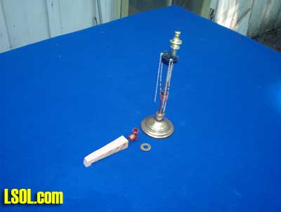
05 - The column is now semi-finished, and the cabinet door fastener snapped on the very top of the column. (In this picture the copper "T" has not been installed, nor has the spout been shaped to size). 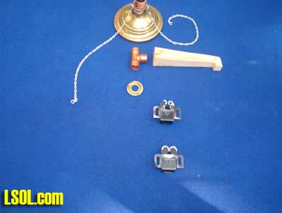
06 - At the bottom is the cabinet door fastener, with the area that must be removed painted in silver (the semi-circular area) as well the two rollers, both in silver. This is done to allow the fastener to clip on the column level, because if the metal is not removed, the column will push the fastener to a 20 degree angle. The second fastener in this view is the completed one, and you can see the area removed by use of a grinding wheel in a Dremel tool.
07 - The column assembled except for the spout. Shape the spout down to circular size by sanding and/or filing and in the wide (inlet) end, bore a 3/8 wide hole. I used a large sharp countersink in a drill for this. Doing this with enough depth that will allow the protruding part of the "T" to pass into the spout and be able to pivot up or down. Drill a 1/16 hole close to the end of the spout, horizontally, and do the same for the protruding "T". Insert a piece of 1/32 wire through the spout and the "T" and crimp over the protruding ends. (Go to picture 08 and zoom in on this and it will clarify this step. Picture 08 will also shown a band going around the lower end of the spout, made from aluminum (or annealed copper wire) that has a 1/6 hole drilled though the top of the band as shown, with one large loop left on, open the loop and pass through the hole in the band, and then take the second chain, remove the large loop, and hook the last link of chain directly to the large loop and bend and crimp back together. Add a pull down of some sort...wire/chain, whatever, to the bottom of the band.
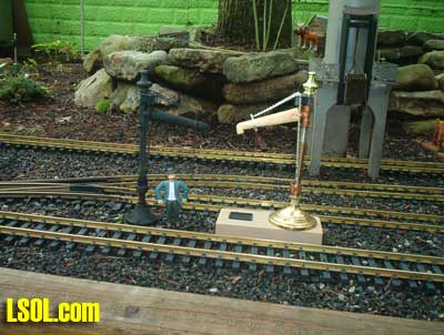
08 - Water Column with the "cement" base, with the black water column on the left in place and is about two years old. 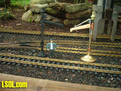
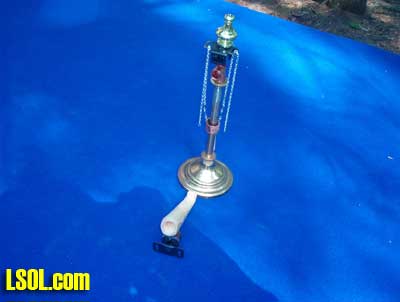
09 - A second picture, but this one without being on the base. To close, Using a 3 1/2 wide base, this water column will serve two tracks, and will clear a train using #4 switches to space out the tracks. Because of the commercial parts used, this may be replicated any number of times to mass-produce more then two or three at a time. Final touches are to paint it a few coats, fully assembled, with flat black spray paint, and perhaps a dusting of "rust" colored undercoat....expect weather to remove paint through the season, and a touch-up each year will keep it looking like, well, old. Hope that you have enjoyed this project, and happy junking and yard sales from the DB&H Rwy.
| Water Column |
| Kirke, Great article. Just shows that detail items for the railroad are easy to construct for readily available bits and pieces. Appreciate you taking the time to pass this information along. |
| Jon D. Miller - 11/07/2007 - 05:31 |
| Water Column |
| Great write up and pictures. Good ole American ingenuity. |
| Barry Reade - 11/07/2007 - 05:53 |
| Water Column |
| Kirke, Really a useful article. Thanks! |
| Jim O'Connor - 11/07/2007 - 11:18 |
| Water Column |
Well done Kirke. When Kirke first told me he had made a standpipe I thought he said sand pipe. I thought he had made some kind of thing for loading sand on to an engine. After he pointed it out on his lay I learned it was for water. Kirke also had me check out the real Standpipe located at the old Western Marland train station in Cumberland MD. This is the starting point for the Western Maryland sicenic Rail Road that runs to Frostburg. |
| John Schwartz (Cap) - 11/07/2007 - 14:13 |
| parts |
| Kirke, wonderful article. You have mastered, or are mastering, the art of seeing model detail parts in other items. This is the skill of a true scratch-builder. I like seeing people do this, 1 because I am cheep and 2 because common items are accessible to everyone, whereas hobby shops aren't. Keep up the good work and informative articles. Thanks |
| David A. Maynard - 11/08/2007 - 15:37 |
| Well Done |
| Great to see articles on the smaller details of everyday railroad life. |
| Rick Henderson - 11/08/2007 - 16:56 |
| DIWWYG |
| DIWWYG to the max! "Do It With What You Got." The best part of any modeling hobby, IMHO. Thanks Kirke for this great article. |
| Phil Benedict - 11/09/2007 - 14:16 |
| Thanks to all.. |
| It's me that wish to thank members of LSOL for their pictures, their comments, and their critiques. A year ago I was intimidated by the scope of submitted articals submited for our use and viewing pleasure, a year later, after two accepted "how to's"......I'm still in awe of the master craftspeople, who can produce a world in miniture, frozen in a time frame, yet full of life. Hats off to all of youse. |
| Kirke Fay - 11/11/2007 - 17:29 |
Top of Page
|


